| Model | Unit | UCG200E | |||
|---|---|---|---|---|---|
| Max. grinding diameter | mm | Φ200 | |||
| Max. grinding length | mm | 500 | 750 | 1000 | |
| Center height | mm | 125 | |||
| Distance between centers | mm | 520 | 765 | 1080 | |
| Max. swiveling diameter | mm | Φ240 | |||
| External grinding range | mm | Φ5-Φ200 | |||
| Internal grinding range | mm | Φ13-Φ80 | |||
| Max. internal grinding length | mm | 125 | |||
| Max. weight between centers | kg | 50 | |||
| Max. loading on chuck | kg | 30 | |||
| Worktable | Max. swing angle (counter-clockwise) | degree | 9° | 8° | 7° |
| Max. swing angle (clockwise) | degree | 9° | 8° | 3° | |
| Range of hydraulic moving speed | m/min | 0.1-3 | |||
| Travel of worktable per revolution | mm | ≈10 | |||
| Wheel head | Max. swing angle (counter-clockwise) | degree | 3 | ||
| Max. swing angle (clockwise) | degree | 3 | |||
| Over travel movement | mm | ≈150 | |||
| Manual feed travel | mm | 70 | |||
| Rapid hydraulic travel | mm | 35 | |||
| Transverse feeding (travel per revolution) | mm | 1 | |||
| Transverse feeding (micro feeding amount) | mm | 0.002 | |||
| Internal grinding tools | Rotation speed of spindle | r/min | 9245,12250,14848 | ||
| External Grinding | Max. diameter of grinding wheel | mm | 400 | ||
| Min. diameter of grinding wheel | mm | 280 | |||
| Width of grinding wheel | mm | 32-50 | |||
| Inner diameter of grinding wheel | mm | 203 | |||
| Max. linear speed of grinding wheel | m/s | 35 | |||
| Internal grinding | Max. size of grinding wheel | mm | 50×32 (OD×W) | ||
| Headstock | Rotation speed of spindle | r/min | 63, 125, 250, 500 | ||
| Max. swing angle (Counter-clockwise) | degree | 90 | |||
| Spindle taper | MT4 | ||||
| Tailstock | Retraction of sleeve | mm | 25 | ||
| Taper of center | MT4 | ||||
| Hydraulic system | Flow of pump | L/min | 14 | ||
| System working pressure | MPa | 0.8-1 | |||
| Capacity of oil tank | L | ≈140 | ≈170 | ≈200 | |
| Coolant system | Flow of oil pump | L/min | 22 | ||
| Capacity of coolant tank | L | 130 | |||
| Motors | Power of external grinding motor | kW | 4 | ||
| Rotation speed of external grinding motor | r/min | 1500 | |||
| Power of internal grinding motor | kW | 0.55 | |||
| Rotation speed of internal grinding motor | r/min | 3000 | |||
| Power of headstock motor | kW | 0.75 | |||
| Rotation speed of headstock motor | r/min | 1000 | |||
| Power of oil pump motor | kW | 1.1 | |||
| Rotation speed of oil pump motor | r/min | 1500 | |||
| Power of coolant motor | kW | 0.125 | |||
| Rotation speed of coolant motor | r/min | 3000 | |||
| Packing dimension | Grinding length 500mm | mm | 2690×2000×2050 | ||
| Grinding length 750mm | mm | 2810×2000×2050 | |||
| Grinding length 1000mm | mm | 3950×2150×2280 | |||
| Net weight | kg | 2020 | 2420 | 3000 | |
| Gross weight | kg | 2730 | 3130 | 3530 | |
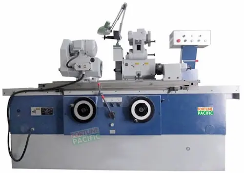
The UCG200E Universal Cylindrical Grinding Machine delivers exceptional precision for OD grinding, ID grinding, taper grinding, and complex profile work. Engineered for demanding workshops, its rigid cast iron construction and hydrostatic spindle ensure vibration-free operation achieving micron-level accuracy (repeatability 0.001mm). Standard with Siemens 840D sl or FANUC 0i-TF Plus CNC, it offers intuitive programming and seamless integration. Key components include the robust bed, precision hydrostatic guides, high-power grinding spindle, automatic wheel dressing unit, and advanced coolant system. With a capacity of Ø200mm x 500mm, it excels in producing hydraulic cylinders, precision shafts, bearing raceways, mold cores, and aerospace components. Users benefit from reduced setup time, superior surface finish (Ra 0.1μm achievable), minimal maintenance needs, and unmatched reliability for high-volume or high-mix production. Its energy-efficient design and ergonomic access enhance productivity.
Универсальный круглошлифовальный станок UCG200E (универсал) обеспечивает высочайшую точность при шлифовке наружных (круглое наружное), внутренних (круглое внутреннее) поверхностей, конических деталей и сложного профиля. Жесткая чугунная станина и гидростатический шпиндель гарантируют виброустойчивость и точность позиционирования до 0.001 мм. Станок с ЧПУ Siemens 840D sl / FANUC 0i-TF Plus позволяет гибко программировать циклы шлифовки коленвалов, валов насосов, втулок подшипников, пресс-форм. Основные узлы: гидростатические направляющие каретки, мощный шлифшпиндель, автоматический правщик круга. Рабочий диапазон Ø200мм x 500мм идеален для инструментального, авиационного, автомобильного производства. Преимущества: минимальное время переналадки, чистота поверхности Ra 0.1 мкм, высокая надежность (надежный станок), энергоэффективность. Идеальное решение для точного шлифования партий любой сложности.
La rectificadora cilíndrica universal UCG200E (rectificadora universal) ofrece precisión extrema para rectificado exterior (rectificado OD), interior (rectificado ID), cónico y de perfiles complejos. Su construcción robusta en fundición y husillo hidrostático aseguran operación sin vibraciones y repetibilidad de 0.001mm. Equipada con CNC Siemens 840D sl / FANUC 0i-TF Plus, permite programación flexible para ejes de transmisión, árboles de levas, camisas de rodamientos, moldes. Componentes clave: guías hidrostáticas, potente cabezal de muela, equilibrador automático de muelas, sistema de refrigeración de alto caudal. Capacidad Ø200mm x 500mm. Excelente para fabricación de componentes hidráulicos, aeroespaciales, automoción. Ventajas: reducido tiempo de preparación (máquina rápida), acabado superficial Ra 0.1μm, bajo mantenimiento, alta productividad. Máquina precisa y fiable para series cortas o largas. Perfecta para talleres de rectificado de precisión y producción industrial.
A retificadora cilíndrica universal UCG200E (retificadora universal) proporciona acabamento de alta precisão para retificação externa (retífica OD), interna (retífica ID), cônica e de perfis complexos. Construção rígida em ferro fundido e eixo hidrostático garantem operação sem vibração e repetibilidade de 0.001mm. Controlada por CNC Siemens 840D sl / FANUC 0i-TF Plus, permite programação fácil para eixos de bombas, virabrequins, moldes, componentes aeroespaciais. Principais componentes: guias hidrostáticas, cabeçote de retificação potente, equipamento automático de dressagem, sistema avançado de refrigeração. Capacidade Ø200mm x 500mm. Ideal para indústria automotiva, hidráulica, moldes, rolamentos. Benefícios: alta produtividade (máquina produtiva), acabamento fino Ra 0.1μm, confiabilidade superior, baixo custo operacional. Máquina robusta e precisa para oficinas de usinagem e produção em série.
Mesin Gerinda Silinder Universal UCG200E (mesin gerinda universal) memberikan presisi tinggi untuk gerinda luar (OD grinding), gerinda dalam (ID grinding), gerinda tirus, dan profil kompleks. Konstruksi besi cor kokoh dan spindle hidrostatik memastikan operasi tanpa getaran dengan akurasi posisi 0.001mm. Dilengkapi CNC Siemens 840D sl / FANUC 0i-TF Plus, mudah diprogram untuk poros engkol (crankshaft), lengan silinder, komponen bearing, cetakan. Kapasitas Ø200mm x 500mm. Komponen utama: bed mesin rigid, slide hidrostatik, spindle gerinda berdaya tinggi, unit dresser roda gerinda otomatis. Aplikasi: komponen otomotif, hidrolik, aerospace, mold tooling. Keunggulan: waktu setup cepat (mesin efisien), hasil permukaan halus Ra 0.1μm, perawatan mudah, keandalan tinggi untuk produksi massal. Mesin presisi hemat energi untuk bengkel dan manufaktur.
دستگاه سنگ زنی استوانه ای یونیورسال UCG200E (دستگاه سنگ یونیورسال) با دقت فوق العاده برای سنگ زنی سطوح خارجی (سنگ OD)، داخلی (سنگ ID)، مخروطی و پروفیل های پیچیده. ساختار مستحکم چدنی و اسپیندل هیدرواستاتیک، عملکرد بدون لرزش و دقت موقعیت دهی 0.001 میلی متر را تضمین می کند. مجهز به CNC زیمنس 840D sl / فانوک 0i-TF Plus، برنامه ریزی آسان برای میل لنگ، شفت پمپ، بوشینگ یاتاقان، قالب. ظرفیت Ø200mm x 500mm. اجزای کلیدی: بستر مستحکم، ریل های هیدرواستاتیک، اسپیندل سنگ قوی، دستگاه اتوماتیک لیسه کشی سنگ. کاربردها: صنایع خودروسازی، هیدرولیک، هوافضا، قالب سازی. مزایا: زمان تنظیم سریع (دستگاه سریع)، پرداخت سطح عالی Ra 0.1μm، تعمیر و نگهداری آسان، قابلیت اطمینان بالا برای تولید انبوه. دستگاه سنگ زنی دقیق و کم مصرف برای کارگاه های تراشکاری و تولید صنعتی.
Máy mài tròn ngoài vạn năng UCG200E (máy mài trụ vạn năng) đạt độ chính xác cực cao cho mài tròn ngoài (mài OD), mài lỗ (mài ID), mài côn và biên dạng phức tạp. Kết cấu gang cứng vững và trục chính thủy tĩnh đảm bảo vận hành không rung, độ lặp lại 0.001mm. Trang bị hệ điều khiển Siemens 840D sl / FANUC 0i-TF Plus, dễ lập trình gia công trục khuỷu, bạc đạn, khuôn mẫu, chi tiết máy bơm. Phạm vi gia công Ø200mm x 500mm. Thành phần chính: băng máy cứng vững, bàn trượt thủy tĩnh, đầu mài công suất cao, hệ thống hiệu chỉnh đá tự động. Ứng dụng: chế tạo xi lanh thủy lực, trục chính, chi tiết máy bay, ô tô. Ưu điểm: thời gian thiết lập nhanh (máy hiệu suất cao), độ nhẵn bề mặt Ra 0.1μm, bảo trì dễ dàng, độ tin cậy cao cho sản xuất hàng loạt. Máy mài chính xác, tiết kiệm năng lượng cho phân xưởng cơ khí.
เครื่องกลึงกลม универсальный UCG200E (เครื่องกลึงกลม) ให้ความแม่นยำสูงสำหรับการกลึงภายนอก (OD grinding), ภายใน (ID grinding), กลึงเอียง และโปรไฟล์ซับซ้อน โครงสร้างเหล็กหล่อแข็งแรงและสปินเดิลไฮโดรสแตติกช่วยลดการสั่นสะเทือน ความเที่ยงตรง 0.001mm ควบคุมด้วย CNC Siemens 840D sl / FANUC 0i-TF Plus ตั้งโปรแกรมง่ายสำหรับเพลาข้อเหวี่ยง, ปลอกแบริ่ง, ชิ้นส่วนแม่พิมพ์ ความสามารถ Ø200mm x 500mm ส่วนประกอบหลัก: เตียงเครื่องมั่นคง, สไลด์ไฮโดรสแตติก, สปินเดิลเพลาแข็งแรง, ระบบลับคมล้ออัตโนมัติ นิยมใช้ในอุตสาหกรรมชิ้นส่วนรถยนต์, ไฮดรอลิก, การบิน, การผลิตแม่พิมพ์ ข้อดี: ตั้งค่าเร็ว (เครื่องประสิทธิภาพสูง), ผิวงานเรียบ Ra 0.1μm, บำรุงรักษาง่าย, ความน่าเชื่อถือสูงสำหรับการผลิตจำนวนมาก เครื่องกลึงกลมประหยัดพลังงานสำหรับโรงงานและเวิร์คช็อป.
Mesin Pengisar Silinder Sejagat UCG200E (mesin pengisar universal) menawarkan ketepatan tinggi untuk pengisaran luaran (OD grinding), dalaman (ID grinding), tirus dan profil kompleks. Binaan besi tuang teguh dan spindel hidrostatik memastikan operasi tanpa getaran, ketepatan 0.001mm. Dikawal CNC Siemens 840D sl / FANUC 0i-TF Plus, mudah diprogram untuk aci engkol, bush galas, komponen acuan. Kapasiti Ø200mm x 500mm. Komponen utama: bed mesin kukuh, peluncur hidrostatik, spindel pengisar berkuasa tinggi, sistem pelaras roda automatik. Aplikasi: komponen hidraulik, aeroangkasa, automotif, acuan. Kelebihan: masa persediaan pantas (mesin cekap), permukaan licin Ra 0.1μm, penyelenggaraan mudah, kebolehpercayaan tinggi untuk pengeluaran isi padu. Mesin pengisar tepat dan jimat tenaga untuk bengkel kejuruteraan dan kilang.
A máquina de retificação cilíndrica universal UCG200E, também conhecida como retificadora universal de alta precisão ou centro de usinagem para retificação cilíndrica, é a solução robusta e confiável para acabamento fino de componentes rotativos. Projetada para máxima rigidez e repetibilidade, esta retificadora de cilindros (retífica cilíndrica universal) permite operações entre pontas ou sem centros com excelência. Com capacidade para peças de até Ø200mm e comprimentos de 500mm, 750mm ou 1000mm entre pontas, garante acabamento superficial excepcional e tolerâncias apertadas de concentricidade, cilindricidade e diâmetro (precisão dimensional). Ideal para eixos, pinos, válvulas e ferramentas na indústria automotiva, aeroespacial e moldes, seu design robusto, sistema hidráulico estável e controles manuais precisos asseguram produtividade elevada e operação segura. Componentes-chave incluem cabeçote fixo e móvel robustos, mesa hidráulica, sistema de avanço transversal preciso e cabeçote da roda de alta potência. Confiabilidade máxima para alta produção ou oficinas de ferramentaria.
Ang UCG200E Universal Cylindrical Grinding Machine, kilala rin bilang high-precision universal grinder o 'de-kalidad na pang-grinda ng shaft', ay ang pangunahing solusyon para sa pinong paggawa ng mga umiikot na parte. Idinisenyo para sa matibay na katumpakan (precision grinding machine) at mataas na bilis ng produksyon, nagagawa nitong i-grinda nang mahusay sa pagitan ng mga sentro o walang sentro. Kayang kumiha ng mga piyesa hanggang Ø200mm at may habang 500mm, 750mm, o 1000mm sa pagitan ng sentro, tinitiyak nito ang napakinis na ibabaw at saktong sukat (high accuracy sa diameter at roundness). Perpekto para sa mga ehe, piston rod, balbula, at kagamitan sa paggawa ng sasakyan, aerospace, at pagmamold. Ang matibay na disenyo nito, stable na hydraulic system, at madaling gamitin na manual controls ay nagsisiguro ng mataas na kahusayan at ligtas na operasyon. Pangunahing bahagi: matibay na headstock at tailstock, hydraulic table, tumpak na cross-feed, at malakas na grinding wheel head. Mataas na reliability para sa mabilis na trabaho o pagawaan ng tool and die.
La rettificatrice cilindrica universale UCG200E, chiamata anche macchina per rettifica cilindrica universale di alta precisione o centro di lavoro per alberi, rappresenta la soluzione affidabile e robusta per la finitura di componenti rotanti. Progettata per massima rigidità e ripetibilità, questa rettificatrice per cilindri (rettificatrice universale) esegue operazioni tra punte o senza centri con precisione eccellente. Capace di lavorare pezzi fino a Ø200mm con lunghezze tra punte di 500mm, 750mm o 1000mm, garantisce finiture superficiali superiori e tolleranze strette di concentricità, cilindricità e diametro (precisione dimensionale). Ideale per alberi, perni, valvole e utensili nell'automotive, aerospaziale e stampi, la sua struttura robusta, sistema idraulico stabile e comandi manuali precisi assicurano elevata produttività e funzionamento sicuro. Componenti principali: testa fissa e mobile robuste, tavola idraulica, avanzamento trasversale preciso e testa motrice della mola potente. Massima affidabilità per produzione intensiva o officine utensili.
UCG200E Universal Silindirik Taşlama Tezgahı, yüksek hassasiyetli evrensel taşlama makinesi veya 'mil taşlama ustası' olarak da bilinir, dönen parçaların ince işlenmesi için güçlü ve güvenilir çözümdür. Maksimum rijitlik ve tekrarlanabilirlik için tasarlanan bu üniversal taşlama makinesi, merkezler arasında veya merkezsiz hassas operasyonlar sunar. Ø200mm çapa ve 500mm, 750mm veya 1000mm merkezler arası uzunluğa kadar parçaları işleyebilir, üstün yüzey kalitesi ve sıkı konsantrisite, silindiriklik ve çap toleransları (yüksek boyutsal hassasiyet) sağlar. Otomotiv, havacılık ve kalıp endüstrilerinde miller, pimler, valfler ve takımlar için idealdir. Sağlam gövdesi, stabil hidrolik sistemi ve hassas manuel kontrolleri yüksek verimlilik ve güvenli kullanım garanti eder. Temel bileşenler: sağlam sabit ve hareketli punta, hidrolik tabla, hassas enine ilerleme ve güçlü taşlama taşı kafası. Yüksek üretim hattı veya takım tezgahı atölyeleri için maksimum dayanıklılık.
La rectifieuse cylindrique universelle UCG200E, également appelée machine à rectifier universelle de haute précision ou centre de rectification pour arbres, est la solution robuste et fiable pour l'usinage fin de composants rotatifs. Conçue pour une rigidité et une répétabilité maximales, cette rectifieuse pour cylindres (rectifieuse universelle) permet des opérations entre pointes ou sans centres avec une précision exceptionnelle. Capable d'usiner des pièces jusqu'à Ø200mm avec des longueurs entre pointes de 500mm, 750mm ou 1000mm, elle garantit un état de surface supérieur et des tolérances serrées de concentricité, cylindricité et diamètre (précision dimensionnelle élevée). Idéale pour les arbres, goupilles, soupapes et outils dans l'automobile, l'aérospatiale et la fabrication de moules, sa construction robuste, son système hydraulique stable et ses commandes manuelles précises assurent une productivité élevée et un fonctionnement sécurisé. Composants clés : poupée fixe et mobile robustes, table hydraulique, avance transversale précise et tête de meule puissante. Fiabilité maximale pour la production intensive ou les ateliers d'outillage.
آلة UCG200E العالمية لطحن الأسطوانات، المعروفة أيضًا باسم آلة الطحن الدقيق عالية الدقة أو مركز تشغيل لعمود الدوران، هي الحل المتين والموثوق للتشطيب الدقيق للمكونات الدوارة. مصممة لتحقيق أقصى صلابة ودقة متكررة، تسمح ماكينة تجليخ الأسطوانات (ماكينة الطحن العالمية) هذه بالعمل بين المراكز أو بدون مراكز بدقة ممتازة. بقدرة على معالجة قطع تصل إلى قطر 200 مم وأطوال بين المراكز 500 مم أو 750 مم أو 1000 مم، تضمن تشطيب سطحي فائق وتحميلات ضيقة للتركيز واستدارة الأسطوانة والقطر (دقة قياسية عالية). مثالية للمحاور والدبابيس والصمامات والأدوات في صناعات السيارات والفضاء والقوالب، يضمن تصميمها القوي، ونظامها الهيدروليكي المستقر، وضوابطها اليدوية الدقيقة إنتاجية عالية وتشغيل آمن. المكونات الرئيسية: رأس ثابت ومتحرك متين، طاولة هيدروليكية، تقدم جانبي دقيق، ورأس عجلة طحن قوي. موثوقية قصوى لخطوط الإنتاج العالي أو ورش تشغيل الأدوات.
Das UCG200E Universalrundschleifmaschine, auch bekannt als Hochpräzisions-Universalschleifmaschine oder Rundschleifzentrum für Wellen, ist die robuste und zuverlässige Lösung für das Feinbearbeiten von Drehteilen. Konzipiert für maximale Steifigkeit und Wiederholgenauigkeit, ermöglicht diese Zylinderschleifmaschine (Universalschleifmaschine) präzises Spitzen- oder spitzenloses Schleifen. Verarbeitet Werkstücke bis Ø200mm bei Spitzenlängen von 500mm, 750mm oder 1000mm und garantiert hervorragende Oberflächengüte sowie enge Toleranzen für Rundlauf, Zylindrizität und Durchmesser (hohe Maßhaltigkeit). Ideal für Wellen, Stifte, Ventile und Werkzeuge in Automobil-, Luftfahrt- und Formenbau. Das robuste Maschinengestell, stabile Hydrauliksystem und präzise Handräder gewährleisten hohe Produktivität und sicheren Betrieb. Schlüsselkomponenten: stabile Spindel- und Reitstockeinheit, hydraulischer Tisch, präziser Quervorschub und leistungsstarkes Schleifspindelaggregat. Maximale Zuverlässigkeit für Hochleistungsfertigung oder Werkzeugbau.
De UCG200E Universele Cilindergrinder, ook bekend als hoog-precisie universele slijpmachine of 'asbewerkingscentrum', is de robuuste en betrouwbare oplossing voor fijnbewerking van roterende onderdelen. Ontworpen voor maximale stijfheid en herhaalbaarheid, biedt deze cilindergrinder (universele slijpmachine) precisiewerk tussen centers of centerloos. Kan onderdelen tot Ø200mm bewerken met centerafstanden van 500mm, 750mm of 1000mm, en garandeert superieure oppervlaktekwaliteit en nauwe toleranties voor concentriciteit, cilindriciteit en diameter (hoge maatnauwkeurigheid). Ideaal voor assen, pennen, kleppen en gereedschappen in auto-, luchtvaart- en matrijzenindustrie. Robuuste constructie, stabiel hydraulisch systeem en nauwkeurige handbediening zorgen voor hoge productiviteit en veilig gebruik. Belangrijkste componenten: stevige kop- en contrasteunkast, hydraulische tafel, precieze dwarsaanslag en krachtig slijpspindelblok. Maximale betrouwbaarheid voor hoogproductie of gereedschapsmakerij.
Szlifierka do wałków UCG200E uniwersalna, znana też jako precyzyjna szlifierka uniwersalna lub centrum do obróbki czopów, to solidne i niezawodne rozwiązanie do wykańczania części obrotowych. Zaprojektowana dla maksymalnej sztywności i powtarzalności, ta szlifierka cylindryczna (szlifierka uniwersalna) umożliwia precyzyjną obróbkę między kłami lub bez kłów. Obróbka detali do Ø200mm przy odległościach kłów 500mm, 750mm lub 1000mm gwarantuje doskonałą gładkość powierzchni i wąskie tolerancje współosiowości, walcowości i średnicy (wysoka dokładność wymiarowa). Idealna do wałów, sworzni, zaworów i narzędzi w motoryzacji, lotnictwie i formownictwie. Solidna konstrukcja, stabilny układ hydrauliczny i precyzyjne sterowanie ręczne zapewniają wysoką wydajność i bezpieczeństwo. Kluczowe elementy: mocna wrzeciono czołowe i ruchowe, stół hydrauliczny, precyzyjny posuw poprzeczny i wydajna głowica szlifierska. Maksymalna niezawodność dla produkcji seryjnej lub narzędziowni.
Mașina de rectificat universală cilindrică UCG200E, cunoscută și sub denumirea de mașină de rectificat universală de precizie sau centru de prelucrare pentru arbori, este soluția robustă și fiabilă pentru finisarea pieselor rotative. Proiectată pentru rigiditate și repetabilitate maximă, această mașină de rectificat cilindru (rectificatoare universală) permite operații între vârfuri sau fără vârfuri cu precizie excepțională. Prelucrează piese până la Ø200mm cu lungimi între vârfuri de 500mm, 750mm sau 1000mm, garantând finisare superficială superioară și toleranțe strânse de concentricitate, cilindricitate și diametru (precizie dimensională ridicată). Ideală pentru arbori, pini, supape și scule în automotive, aerospațial și matrițe. Construcția robustă, sistemul hidraulic stabil și comenzile manuale precise asigură productivitate ridicată și funcționare sigură. Componente cheie: cap fix și mobil robuste, masă hidraulică, avans transversal precis și cap port-piatră puternic. Fiabilitate maximă pentru producție intensivă sau ateliere de scule.
Univerzális hengercsiszoló gépek UC-G200E professzionális megoldás 200x500 mm munkadarabokhoz. Hidraulikus orsóvezeték, automata kerékjavító és digitális mérési rendszer garantálja a ±0.001 mm-es precíziót. Nagy teljesítményű köszörülő motor, pormentes szigetelés és Szoftvervezérelt PLC vezérlés ideális hengerfelületekhez, kúpokhoz és homlokfelületekhez. Ipari alkatrészek, csapágygyűrűk és szerszámgyártás számára. Energiatakarékos hajtás 30%-al alacsonyabb üzemeltetési költséggel. Tartós öntöttvas szerkezet minimalizálja a rezgéseket a finom felületi simaság érdekében.
Καθολικοί κυλινδρικοί τροχοί UCG-200E παρέχουν ακριβή λείανση μεχρι 0.001 mm για έργα μέχρι 500mm. Υδραυλικό τραπέζι, αυτόματη διόρθωση τροχού και CNC ελέγχου διασφαλίζουν σταθερότητα σε μαζική παραγωγή εξαρτημάτων. Ιδανικά για ατμομηχανές, αεροδιαστημικά εξαρτήματα και καλούπια. Σύστημα αυτόματης λίπανσης, θερμοκρασιακή αντιστάθμιση και αντιδονητικό πλαίσιο βελτιώνουν την αξιοπιστία. Χαμηλής κατανάλωσης κινητήρες 7.5kW με συχνόμετρο ελέγχου ταχύτητας. Λέσχες αναζήτησης: κύλινδρος λείανσης μηχανήματα, CNC φυγοκεντρικοί τροχοί, βιομηχανική ακριβείας λείανσης εξοπλισμός.
Univerzální brusky na válce UC-G200E s pracovním rozsahem Ø200x500mm dosahují přesnosti 1 mikronu. Automatické posuvy, řídicí systém Fanuc a vyvažování brusných kotoučů online optimalizují produktivitu. Robustní litinová konstrukce s tepelnou stabilitou pro těžké obrábění ložiskových pouzder, hřídelů a kuželových ploch. Energeticky účinný pohon šetří až 25% nákladů. Bezúdržbová hydrodynamická ložiska, digitální posuv měřidla a protivibrační systémy zajišťují hladkost Ra0.2μm. Vyhledávané klíčová slova: CNC brusky válcové, průmyslové brusné automaty, přesné obrábění oceli.
Универсални цилиндрични шлайфмашини UCG200E с капацитет 200x500mm. Високоскоростно шлифоване до 0.001mm точност с автоматична корекция на колелото и ЧПУ Fanuc управление. Хидравлична система, термокомпенсирани шпиндели и антивибрационна станина за автомобилни компоненти и аерокосмически части. Директно задвижване 10kW, цифров измерителен прибор Marposs и автоматично съхранение на данни. Спестяване на енергия 30%, подходящ за масово производство на валове, втулки и зъбни колела. Популярни търсения: CNC шлайфовъчни машини, индустриално шлифоване, прецизни метални детайли.
Универзалне цилиндричне брусилице UCG-200E за обраду до 500mm дужине. Хидравлични клизни столови, аутоматско оштравање алатки и дигитална мерења постижу тачност од ±0.001mm. Фанук контролер, термостабилизовани вретена и антивибрациони носачи за производницу осовина, лежајевих прстенова и коничних површина. Енергетски ефикасан мотор 7.5kW са променљивом брзином за уштеду до 25%. Трајна конструкција од левеног гвожђа за Ra0.1μm фину завршну обраду. Кључне фразе: индустријски брусили, прецизна обрада метала, CNC цилиндричне машине.
Univerzálne brúsky na valce UC-G200E s rozsahom Ø200x500mm. Automatické posuvy, systém vyvažovania kolies a digitálne meracie zariadenie zabezpečujú mikrónovú presnosť. CNC ovládanie, hydrostatické vretená a tepelná kompenzácia pre brúsenie hriadeľov, kužeľových plôch a ložiskových krúžkov. Nízkonákladový prevod s frekvenčným meničom šetrí 30% energie. Odolný liatinový rám s antivibračným systémom pre hladkosť Ra0.2μm. Vyhľadávané výrazy: CNC brúsiace stroje, priemyselné brúsenie, presná obrábka ocele.
Univerzalne cilindrične brusilice UCG200E za precizno brušenje do 500mm. Hidraulični klizni stolovi, automatsko oštrenje alata i Fanuc sustav upravljanja osiguravaju točnost od 0.001mm. Digitalno mjerenje, termokompenzirani vreteni i protuvibracijski nosači za proizvodnju ležajeva, osovina i konusnih površina. Energetski učinkovit motor 7.5kW s frekvencijskim pretvaračem. Trajno lijevano željezo konstrukcije za finu obradu površine Ra0.1μm. Ključne riječi: CNC brusilice, industrijsko brušenje metala, precizna obradba.
Univerzalni valjčni brusilni stroji UC-G200E z delovnim obsegom 200x500mm. Avtomatski pomiki, sistem za uravnoteženje koles in digitalni merilni sistem zagotavljajo natančnost ±0.001mm. CNC krmiljenje, hidrostatična vretena in termokompenzacija za brušenje gredi, ležajnih obročev in stožčastih površin. Varčevanje z energijo do 30% s frekvenčnim pretvornikom. Vibracijsko dušena konstrukcija iz litine za hrapavost Ra0.2μm. Iskalni izrazi: CNC brusilni stroji, industrijska obdelava kovin, visoko natančno brušenje.
Універсальні круглошліфувальні верстати UCG200E з робочим діапазоном Ø200x500мм. Гідравлічні столи, автоматична правка кола та ЧПУ Fanuc забезпечують точність 1 мкм. Термокомпенсовані шпінделі, цифровий вимірювальний прилад Marposs та віброізольована станина для обробки валів, втулок та конічних поверхонь. Енергоефективний привід 7.5кВт з частотним перетворювачем. Конструкція з чавунного лиття забезпечує чистоту поверхні Ra0.1μm. Поширені запити: верстати для шліфування, промислове шліфування металів, прецизійна обробка деталей.