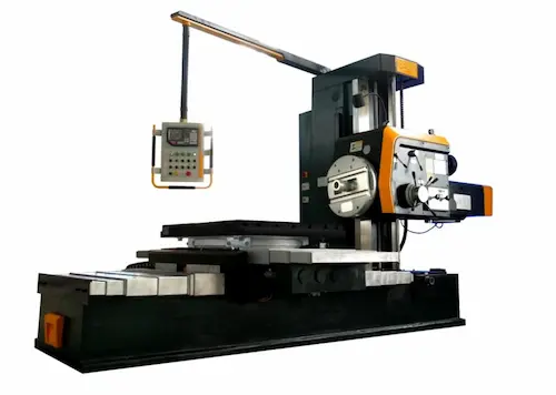
Ismerje meg a Fortune Pacific FPX6111B horizontális fúró-maró gépet – a nehézipari gyártás csúcstechnológiája! Ez a prémium minőségű univerzális megmunkáló központ kiválóan alkalmazható nagy méretű alkatrészek precíz fúrására, marására, esztergálására és megmunkálására. A robusztus öntöttvas szerkezet, a nagy teljesítményű főorsó (2000 ford./perc) és a kiterjedt X/Y/Z-tengelyek (2000/1600/1600 mm) kivételes stabilitást és merevséget biztosítanak 0.01 mm-es ismételhető pontossággal. Tartalmazza a nagy kapacitású CNC vezérlőrendszert, nagy teherbírású lineáris vezetőket, precíz forgóasztalt és erős szerszámváltót. Ideális megoldás energia-, légi-, űr- és gépipari alkatrészek, valamint szerszámgépek gyártásához. Fő előnyei: kiemelkedő megmunkálási hatékonyság, kiváló felületi minőség, kifogástolható megbízhatóság és alacsony üzemeltetési költség. Építőelemek: merev alapgép, nagy átmérőjű kúpos orsó, precíziós golyósorsós hajtások, zárt hűtőrendszer. Válassza a tartósságot és a csúcsminőséget! Fedezze fel ezt a kiváló fúró-maró megoldást ma!
Ανακαλύψτε το Fortune Pacific FPX6111B Οριζόντιο Γερασκότρυπανο-Φρέζα – η κορυφαία λύση για βαρύ μηχανολογικό επεξεργασία! Αυτό το βιομηχανικό CNC μηχάνημα κάθετης και οριζόντιας επεξεργασίας προσφέρει απαράμιλλη ακρίβεια (επαναλαμβανόμενο 0.01 mm) για μεγάλα έργα όπως μπλοκ κινητήρων, ατμοστρόβιλοι και αεροδιαστημικά εξαρτήματα. Εξοπλισμένο με ισχυρό κύριο άξονα (2000 σ.α.λ.), μακριά ολισθητήρα και εκτεταμένες διαδρομές άξονα Χ/Υ/Ζ (2000/1600/1600 mm), εξασφαλίζει σταθερότητα και αντοχή. Το ισχυρό χυτοσίδηρο πλαίσιο, τα ακριβή γραμμικά ρουλεμάν και ο αδιάβροχος ηλεκτρολογικός εξοπλισμός εγγυώνται μακροχρόνια αξιοπιστία. Βασικά στοιχεία: αδιάβροχο κουτί ταχυτήτων, περιστροφικός πίνακας υψηλής φόρτισης, αυτόματο σύστημα αλλαγής εργαλείων, σύγχρονο CNC σύστημα ελέγχου. Ιδανικό για κατεργασία μεγάλων επιφανειών, βαθιές οπές, νήματα και σύνθετες επιφάνειες. Πλεονεκτήματα: υψηλή παραγωγικότητα, άριστη ποιότητα επιφάνειας, ελαχιστοποιημένες χρόνοι διακοπής λειτουργίας. Επενδύστε στην τεχνολογία άκρης ακρίβειας για τη βιομηχανία σας!
Představujeme horizontální vyvrtávačku a frézku Fortune Pacific FPX6111B – špičkové univerzální obráběcí centrum pro těžké obrábění! Tento robustní stroj CNC je dokonalý pro přesné vrtání, frézování, soustružení a obrábění rozměrných součástí, jako jsou skříně převodovek, formy či hydraulické komponenty. Disponuje výkonným vřetenem (2000 ot./min), dlouhým vřetenovým suportem a velkým pracovním rozsahem X/Y/Z (2000/1600/1600 mm) s opakovatelnou přesností 0.01 mm. Klíčové komponenty: vysoce tuhá litinová konstrukce, přesná lineární vedení, digitální čtecí systém, výkonný automatický nástrojový měnič a otočný stůl s vysokou nosností. Vyniká v náročných aplikacích leteckého, energetického a automobilového průmyslu. Hlavní výhody: výjimečná odolnost, minimální vibrace, vysoká účinnost řezání a snadná obsluha díky modernímu řídicímu systému. Konfigurace zahrnuje chladicí systém, chipový dopravník a osové pohony s vysokým kroutícím momentem. Získejte špičkový vyvrtávací a frézovací stroj pro maximální produktivitu vaší dílny!
Открийте хоризонталната пробивна и фрезовална машина Fortune Pacific FPX6111B – идеалното решение за тежката промишленост! Този високоточни CNC металорежещ център (повторяемост 0.01 mm) е проектиран за обработка на големи детайли: корпуси, матрици, турбини. С впечатляващ работен обхват по осите X/Y/Z (2000/1600/1600 mm), мощен шпиндел (2000 об/мин) и здрава чугунена конструкция, машината гарантира стабилност при интензивни операции. Основни елементи: високо товароспособен въртящ се маса, автоматична смяна на инструменти, цифрова индикация, затворена водна охладителна система. Перфектна за фрезоване, пробиване, разсточване, нарязване на резби. Ключови предимства: изключителна производителност, висока коравина, намалени вибрации, дълъг експлоатационен живот. Приложения: енергетика, корабостроене, тежко машиностроене. Конфигурации включват СОЖ помпа, линейни водачи с висока точност и ЧПУ система за пълен контрол. Изберете надеждност и прецизност за вашия цех!
Upoznajte Fortune Pacific FPX6111B horizontalnu glodalicu-bušilicu – vrhunsko rešenie za teško industrijsko mašinstvo! Ovaj izuzetno precizan CNC alatni stroj (ponavljanje 0.01 mm) namenjen je bušenju, glodanju i tokarenju velikih komponenti kao što su kalupi, oklopi ili mašinski delovi. Sa impresivnim radnim hodom X/Y/Z (2000/1600/1600 mm), snažnim glavnim vretenom (2000 o/min) i čvrstom konstrukcijom od livenog gvožđa, obezbeđuje stabilnost i izdržljivost. Ključni delovi: visoko nosivi rotirajući sto, automatski izmenjivač alata, digitalni sistem za očitavanje, zatvoreni sistem za hlađenje. Idealna za preciznu obradu u avio, automobilskoj i naftnoj industriji. Prednosti: izvanredna produktivnost, minimalne vibracije, jednostavno korišćenje zahvaljujući modernom CNC upravljaču. Standardna konfiguracija uključuje pumpu za emulziju, linearna vodilja visoke preciznosti i sistem za odvod strugotine. Obrađujte čelik, liveno gvožđe i legure sa maksimalnom efikasnošću. Investirajte u pouzdanost!
Objavujeme horizontálne vŕtačko-frézovacie stredisko Fortune Pacific FPX6111B – špičkové CNC obrábacie centrum pre ťažké obrábanie! Tento vysoko presný stroj (opakovateľnosť 0.01 mm) je dokonalý pre vŕtanie, frézovanie a sústruženie rozmerných súčiastok ako sú formy, prevodovky alebo hydraulické bloky. Disponuje výkonným vretenom (2000 ot./min), dlhým posuvným stolom a veľkým pracovným rozsahom X/Y/Z (2000/1600/1600 mm). Robustná liatinová konštrukcia, presné lineárne vedenie a výkonný automatický výmenník nástrojov zaisťujú stabilitu a dlhú životnosť. Aplikácie: letecký priemysel, energetika, výroba formovacích strojov. Výhody: mimoriadna účinnosť, vynikajúca kvalita opracovanej plochy, nízku hlučnosť a jednoduchá údržba. Štandardná konfigurácia zahŕňa chladiaci systém, dopravník triesok a digitálne snímače polohy. Optimalizujte svoju výrobu s touto spoľahlivou frézovacou a vŕtacou jednotkou!
Predstavljamo horizontalnu glodalicu-bušilicu Fortune Pacific FPX6111B – vrhunsko CNC glodalno središte za teško industrijsko strojarstvo! Ovaj iznimno precizan alatni stroj (ponavljanje 0.01 mm) namijenjen je bušenju, glodanju i tokarenju velikih komponenti kao što su kućišta, kalupi ili hidraulički blokovi. S impresivnim hodom X/Y/Z (2000/1600/1600 mm), snažnim glavnim vretenom (2000 o/min) i robusnom konstrukcijom od lijevanog željeza, osigurava stabilnost i dugotrajnost. Ključni dijelovi: visoko nosivi rotacijski stol, automatski izmjenjivač alata, digitalni sustav za očitanje, zatvoreni sustav hlađenja. Idealna za preciznu obradu u zrakoplovnoj, automobilskoj i energetskoj industriji. Prednosti: izvanredna produktivnost, minimalne vibracije, jednostavno korištenje zahvaljujući modernom CNC upravljaču. Standardna konfiguracija uključuje pumpu za emulziju, linearna vodilja visoke preciznosti i sustav za odvod strugotine. Obrađujte čelik, lijevano željezo i legure s maksimalnom učinkovitošću. Poboljšajte svoju proizvodnju!
Spoznajte horizontalno vrtalno-glosanje stroj Fortune Pacific FPX6111B – vrhunska rešitev za težko industrijsko obdelavo! Ta izjemno natančen CNC stroj (ponovljivost 0.01 mm) je namenjen vrtanju, glodanju in struženju velikih komponent, kot so ohišja, modeli ali hidravlični bloki. Z impresivnim delovnim obsegom X/Y/Z (2000/1600/1600 mm), zmogljivim glavnim vretenom (2000 vrt/min) in trdno konstrukcijo iz litega železa zagotavlja stabilnost in trajnost. Ključne komponente: visoko nosilni rotacijski miza, samodejni menjalnik orodja, digitalni sistem za odčitavanje, zaprt sistem za hlajenje. Idealno za natančno obdelavo v letalski, avtomobilski in energetski industriji. Prednosti: izjemna produktivnost, minimalne vibracije, enostavna uporaba zahvaljujoč sodobnemu CNC krmilniku. Standardna konfiguracija vključuje črpalko za emulzijo, linearne vodila visoke natančnosti in sistem za odstranjevanje ostankov. Obdelujte jeklo, lito železo in zlitine z največjo učinkovitostjo. Nadgradite svojo delavnico!
Відкрийте для себе горизонтально-розточувальний та фрезерний верстат Fortune Pacific FPX6111B – ідеальне рішення для важкої промисловості! Цей високоточний верстат з ЧПУ (повторюваність 0.01 мм) призначений для свердління, фрезерування та токарної обробки великогабаритних деталей: корпусів, прес-форм, турбін. Має великий робочий діапазон по осях X/Y/Z (2000/1600/1600 мм), потужний шпиндель (2000 об/хв) та міцну чавунну конструкцію станини, що забезпечує стабільність під час інтенсивних операцій. Основні компоненти: високовантажний поворотний стіл, автоматичний змінник інструменту, цифрова індикація, закрита система охолодження. Ідеальний для фрезерування, свердління, розточування, нарізання різьблення. Ключові переваги: виняткова продуктивність, висока жорсткість, знижені вібрації, довгий термін служби. Застосування: енергетика, авіабудування, важке машинобудування. Конфігурація включає помпу СОЖ, лінійні напрямні високої точності та систему ЧПУ для повного контролю. Обирайте надійність та точність для вашого цеху!