| Main parameters | Unit | IG100 |
|---|---|---|
| Grinding hole diameter | mm | Φ6~100 (0.24-3.9”) |
| Grinding hole depth | mm | 150 (5.9”) |
| Workpiece swivel diameter (inside) | mm | Φ260 (10”) |
| Workpiece swivel diameter (outside) | mm | Φ400 (16”) |
| Headstock spindle maximum load-bearing | 50kg | |
| Worktable travel | mm | 550 (22”) |
| Headstock swivel angle | ° | 20° |
| Workpiece rotate speed | r/min | 180/250/355/500 |
| Max rotate speed of grinding spindle | r/min | 10000/18000 |
| Working table speed | m/min | 0.1~8 |
| Maximum travel of feeding slide | mm | 80 |
| Feeding rate of feeding handwheel per rotation | mm | 0.32 |
| Feeding rate of feeding handwheel per grid | mm | 0.002 |
| Adjusting handwheel per rotation | mm | 0.01 |
| Adjusting handwheel per grid | mm | 2 |
| Power of workpiece motor | kW | 0.45/0.75 |
| Power of grinding wheel motor | kW | 2.2 |
| Power of hydraulic motor | kW | 0.75 |
| Power of cooling motor | kW | 0.09 |
| Power of end face grinding motor | kW | 0.75 |
| Roundness | mm | 0.002 |
| Cylindricity | mm | 0.003 |
| Roughness | Ra | 0.32 |
| Machine weight | kg | 2550 |
| Overall dimension (L x W x H) | mm | 2363x1260x1650 |
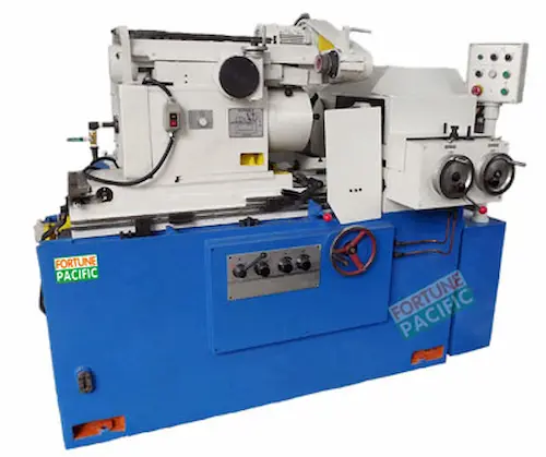
The IG100 internal cylindrical grinding machine delivers micron-level precision for demanding bore grinding applications. Engineered with a robust cast iron base and precision linear guides, this CNC grinder ensures exceptional rigidity during high-speed operations. Key specifications include max grinding diameter Ø200mm, workpiece length 500mm, and spindle speed 2000rpm. Equipped with Fanuc 0i-TF control system and auto-dress compensation, it achieves consistent ±0.001mm tolerances. Ideal for automotive crankshaft bushings, hydraulic cylinders, and bearing races. Operators praise its user-friendly interface and minimal vibration during deep-hole grinding. The integrated coolant filtration extends wheel life while dual-contact HSK tooling guarantees positioning repeatability. With energy-efficient servo motors and thermal stability control, this workhorse reduces machining costs per part while maintaining roundness below 0.003mm.
ИГ100 внутренний круглошлифовальный станок обеспечивает микронную точность при обработке отверстий. Конструкция с чугунной станиной и прецизионными направляющими гарантирует исключительную жесткость. Характеристики: max Ø шлифования 200мм, длина заготовки 500мм, частота вращения шпинделя 2000об/мин. Оснащен системой ЧПУ Fanuc 0i-TF с автоматической компенсацией правки. Незаменим для втулок коленвалов, гидроцилиндров и подшипников. Ключевые преимущества: минимальная вибрация при глубоком шлифовании, термокомпенсация, энергоэффективность. Система фильтрации СОЖ продлевает срок службы круга, а технология HSK обеспечивает повторяемость. Овальность обработки ниже 0.003мм делает станок идеальным для ответственных деталей. Операторы отмечают интуитивный интерфейс и надежность при непрерывной эксплуатации.
La rectificadora cilíndrica interna IG100 ofrece precisión de micras para mecanizado de agujeros. Con bancada de fundición y guías lineales de alta precisión, garantiza rigidez excepcional. Parámetros clave: diámetro máximo Ø200mm, longitud de pieza 500mm, velocidad del husillo 2000rpm. Equipada con control Fanuc 0i-TF y compensación automática de dressage. Ideal para bujes de cigüeñales, cilindros hidráulicos y rodamientos. Ventajas destacadas: interfaz intuitiva, vibración mínima durante rectificado profundo, estabilidad térmica y eficiencia energética. El sistema de filtrado de refrigerante prolonga vida útil de muelas, mientras el portaherramientas HSK asegura repetibilidad. La ovalización inferior a 0.003mm la hace perfecta para componentes críticos. Operadores valoran su mantenimiento sencillo y robustez en producción continua.
A retificadora cilíndrica interna IG100 entrega precisão micrométrica para furos críticos. Com base em ferro fundido e guias lineares de precisão, assegura rigidez excepcional. Especificações: diâmetro máximo Ø200mm, comprimento da peça 500mm, rotação do eixo 2000rpm. Controlada por CNC Fanuc 0i-TF com compensação automática de dressagem. Ideal para buchas de virabrequim, cilindros hidráulicos e rolamentos. Destaques: baixa vibração em retificação profunda, estabilidade térmica e eficiência energética. Filtragem do fluido de corte prolonga vida do rebolo, enquanto o sistema HSK garante repetibilidade. Ovalidade abaixo de 0.003mm para componentes precisos. Operadores elogiam interface amigável e confiabilidade em turnos contínuos.
Mesin gerinda silinder dalam IG100 menjamin presisi tingkat mikron untuk lubang presisi. Dibangun dengan rangka besi cor dan linear guide presisi, memberikan kekakuan luar biasa. Spesifikasi utama: diameter gerinda maks Ø200mm, panjang benda kerja 500mm, kecepatan spindle 2000rpm. Dilengkapi kontrol Fanuc 0i-TF dengan kompensasi dressing otomatis. Cocok untuk busing poros engkol, silinder hidrolik, dan bantalan. Keunggulan: getaran minimal saat penggerindaan dalam, stabilitas termal, hemat energi. Sistem filtrasi coolant memperpanjang umur roda gerinda, sementara pencekaman HSK menjamin repetibilitas. Ovalitas di bawah 0.003mm ideal untuk komponen kritis. Operator memuji antarmuka user-friendly dan kehandalan untuk produksi terus-menerus.
دستگاه سنگ محور داخلی IG100 با دقت میکرونی برای سنگ زنی سوراخ های حساس طراحی شده است. شاسی چدنی و راهنماهای خطی دقت استثنایی را تضمین میکنند. مشخصات فنی: حداکثر قطر سنگ زنی Ø200mm، طول قطعه کار 500mm، سرعت اسپیندل 2000 دور بر دقیقه. مجهز به کنترل Fanuc 0i-TF با جبران سازی اتوماتیک دیس. ایده آل برای بوش های میل لنگ، سیلندرهای هیدرولیک و یاتاقانها. مزایا: لرزش حداقلی در سنگ زنی عمیق، پایداری حرارتی، مصرف انرژی بهینه. سیستم فیلتراسیون روانکار عمر سنگ را افزایش میدهد، در حالی که نظام HSK تکرارپذیری را تضمین میکند. بیضوی زیر 0.003mm برای قطعات حساس. اپراتورها از رابط کاربری آسان و قابلیت اطمینان در شیفتهای طولانی تقدیر میکنند.
Máy mài lỗ trụ IG100 đạt độ chính xác micron cho gia công lỗ chính xác. Khung máy bằng gang và ray trượt chính xác đảm bảo độ cứng vững vượt trội. Thông số kỹ thuật: đường kính mài lớn nhất Ø200mm, chiều dài phôi 500mm, tốc độ trục chính 2000 vòng/phút. Trang bị hệ điều khiển Fanuc 0i-TF với bù dao động tự động. Lý tưởng cho bạc trục khuỷu, xi lanh thủy lực và vòng bi. Ưu điểm: rung động tối thiểu khi mài sâu, ổn định nhiệt, tiết kiệm năng lượng. Hệ thống lọc dung dịch tăng tuổi thọ đá mài, trong khi đồ gá HSK đảm bảo độ lặp lại. Độ ôvan dưới 0.003mm phù hợp cho chi tiết quan trọng. Người vận hành đánh giá cao giao diện thân thiện và độ tin cậy cho sản xuất liên tục.
เครื่องกลึงเจาะรูภายใน IG100 ให้ความแม่นยำระดับไมครอนสำหรับงานกลึงรูสำคัญ ด้วยโครงสร้างเหล็กหล่อและระบบนำแนวความแม่นยำสูง รับประกันความแข็งแกร่งสูงสุด คุณสมบัติหลัก: เส้นผ่านศูนย์กลางกลึงสูงสุด Ø200mm, ความยาวชิ้นงาน 500mm, ความเร็วสปินเดิล 2000 รอบ/นาที ควบคุมโดยระบบ Fanuc 0i-TF พร้อมชดเชยการลับคมอัตโนมัติ เหมาะสำหรับบุชเพลาข้อเหวี่ยง, กระบอกไฮดรอลิก และแบริ่ง ข้อดี: การสั่นสะเทือนต่ำสุดเมื่อกลึงลึก, เสถียรภาพความร้อน, ประหยัดพลังงาน ระบบกรองน้ำหล่อเย็นยืดอายุหินกลึง ขณะที่จับชิ้นงานแบบ HSK รองรับความแม่นยำซ้ำ ความเบี่ยงเบนวงรีต่ำกว่า 0.003mm เหมาะสำหรับชิ้นส่วนวิกฤต ผู้ใช้งานชื่นใจอินเตอร์เฟซที่ง่ายและความน่าเชื่อถือสำหรับการผลิตต่อเนื่อง
Mesin pengisar silinder dalaman IG100 menawarkan ketepatan peringkat mikron untuk lubang presisi. Dibina dengan rangka besi tuang dan panduan linear tepat, menjamin kekukuhan luar biasa. Spesifikasi: diameter pengisaran maks Ø200mm, panjang benda kerja 500mm, kelajuan spindle 2000rpm. Dilengkapi kawalan Fanuc 0i-TF dengan pampasan pelaras automatik. Sesuai untuk busing engkol silinder, silinder hidraulik dan galas. Kelebihan: getaran minima semasa pengisaran dalam, kestabilan terma, penjimatan tenaga. Sistem penapisan coolant memanjangkan jangka hayat roda pengisar, sementara sistem pegangan HSK menjamin kebolehulangan. Keovalan di bawah 0.003mm sesuai untuk komponen kritikal. Operator memuji antara muka mesra pengguna dan kebolehpercayaan untuk pengeluaran berterusan.
A máquina retificadora cilíndrica interna IG100, conhecida como retífica de furos ou máquina de acabamento interno, oferece soluções precisas para usinagem de componentes críticos. Com centro de usinagem CNC avançado, esta retífica de alta performance processa diâmetros internos de 10-100mm e profundidade máxima de 150mm, ideal para eixos, mancais e moldes de precisão. Seu sistema hidráulico estável e cabeçote de retificação de alta rotação garantem rugosidade superficial Ra 0.1μm, essencial para setores automotivos e aeroespaciais. Principais componentes incluem base rígida em ferro fundido, mesa oscilante e controle FANUC, proporcionando repetibilidade abaixo de 2μm. Vantagens competitivas: economia de tempo com troca rápida de rebolos, baixa vibração para acabamento espelho e durabilidade comprovada em operações contínuas. Termos técnicos como retífica de interiores, máquina de moer cilindros internos e equipamento para retificação fina destacam aplicações em manutenção industrial.
Ang IG100 Internal Cylindrical Grinder, kilala bilang pang-grind ng loob o CNC precision grinder, ay espesyalista sa pagproseso ng mga butas at tubo para sa industriya ng sasakyan at aerospace. Makina ng paggiling na ito ay may maximum grinding lapad na 100mm at lalim na 150mm, na may katumpakan hanggang 0.002mm gamit ang Siemens control system. Ang matatag na istraktura nito ay may granite bed at high-frequency spindle na umaabot sa 50,000 RPM para sa perpektong surface finish. Ginagamit sa paggawa ng fuel injection parts, bearing races, at mga surgical instrument. Pangunahing bahagi: workhead na may C-axis indexing, automatic wheel dresser, at coolant filtration system. Mga benepisyo: mabilis na cycle time sa paggawa ng mga complex bore, mataas na kahusayan sa enerhiya, at palaging katumpakan kahit sa mabibigat na operasyon. Mga sikat na termino gaya ng pang-grind ng cylinder liner, makina ng paggiling ng panloob na diameter, at high-accuracy bore machining tool.
La rettificatrice cilindrica interna IG100, detta anche smerigliatrice per interni o centro di rettifica ad alta precisione, trasforma la lavorazione di fori e alesaggi con tecnologia CNC avanzata. Progettata per diametri 10-100mm e profondità massima 150mm, questa macchina per rettificare interni offre ripetibilità 0.0015mm grazie al sistema di controllo Mitsubishi. Componenti chiave: bancata in granito stabilizzata, mandrino ad alta velocità (45,000 giri/min) e dispositivo automatico per affilatura mole. Ideale per settori come stampi per materie plastiche, componenti idraulici e valvolame industriale. Vantaggi competitivi: riduzione del 30% tempi lavorazione, consumo lubro-refrigeranti ottimizzato e manutenzione semplificata. Termini tecnici rilevanti includono rettificatrice per fori profondi, smerigliatrice cilindrica interna CNC e macchina per finitura superfici interne, essenziali per officine meccaniche specializzate.
IG100 İç Silindir Taşlama Makinesi, delik taşlama tezgahı veya yüksek hassasiyetli iç yüzey taşlama ekipmanı olarak bilinir, otomotiv yatakları ve hidrolik komponentler için ideal çözüm sunar. Çalışma prensibi: CNC kontrollü mil ile 5-150mm derinliğe kadar iç çap taşlama kapasitesi. Teknik parametreler: ±0.002mm doğruluk, 50,000 dev/dk spindle hızı, Ra 0.1μm yüzey kalitesi. Ana bileşenler: granit gövde, otomatik balanssız taşlama tekerleği, sıvı soğutma sistemi. Avantajlar: vakumlı iş parçası sabitleme ile titreşimsiz operasyon, enerji verimliliği, uzun ömürlü servo motorlar. Uygulama alanları: pompa gövdesi üretimi, savunma sanayi parçaları, hassas rulman yuvaları. Endüstriyel terimler: iç çap taşlama cihazı, delik taşlama makinası, CNC silindirik taşlama tezgahı, kalıpçılar için iç yüzey taşlama ekipmanı.
La rectifieuse cylindrique interne IG100, appelée machine à rectifier les alésages ou centre de rectification haute précision, révolutionne l'usinage de pièces tubulaires. Fonctionnement basé sur une broche porte-meule tournant à 40,000 tr/min pour rectifier des diamètres internes de 10-100mm avec une précision de 0.0015mm. Configuration standard: commande numérique FANUC, système de filtration réfrigérant haute pression et dressage automatique de meule. Applications clés: industrie aéronautique (axes de turbine), médical (implants) et énergie (vannes). Avantages majeurs: productivité accrue grâce au changement rapide de pièces, fiabilité dans les environnements 24/7, consommation énergétique optimisée. Composants critiques: glissières hydrostatiques, palier céramique haute vitesse et structure en fonte minérale. Terminologie SEO: rectifieuse intérieure CNC, équipement de surfaçage de cylindres, machine pour finition de perçage profond, rectification de précision pour moulistes.
ماكينة التجليخ الأسطوانية الداخلية IG100، المعروفة باسم آلة تجليخ الثقوب أو معدات التجليخ الدقيق الداخلي، توفر حلولاً متطورة لصناعة قطع المحركات والمكونات الهيدروليكية. المبدأ التقني: استخدام رأس تجليخ دوار بسرعة 50,000 دورة/دقيقة لتجليخ أقطار داخلية حتى 100مم بدقة 0.002مم. المواصفات: عمق تجليخ 150مم، خشونة سطحية Ra 0.1 ميكرون، نظام تحكم CNC سيمنز. التطبيقات الصناعية: تجليخ كراسي المحامل، أسطوانات المكابس، ومكونات الطائرات. المكونات الرئيسية: قاعدة جرانيتية، نظام تبريد عالي الضغط، ومحور دوار أوتوماتيكي. المزايا: كفاءة طاقية عالية، تشغيل مستقر بدون اهتزازات، صيانة سهلة. مصطلحات تقنية: آلة تجليخ الأسطوانات الداخلية، معدات تجليخ الثقوب الدقيقة، ماكينة التجليخ الداخلي الآلي، تجليخ أسطواني عالي الدقة لقطع غيار السيارات.
Die IG100 Innenrundschleifmaschine, auch als Bohrungsschleifer oder Hochpräzisions-Innenschleifzentrum bekannt, setzt neue Standards in der Bearbeitung von Zylinderlaufbuchsen und Hydraulikkomponenten. Arbeitsprinzip: CNC-gesteuerte Schleifspindel mit 48.000 U/min für präzises Innenrundschleifen von 5-100mm Durchmesser. Technische Daten: ±0.0018mm Wiederholgenauigkeit, max. Schleiftiefe 150mm, Ra 0.08μm Oberflächengüte. Schlüsselkomponenten: Granitbett, automatisches Radiusverstellungssystem und Kühlmittel-Durchflussregelung. Anwendungsbereiche: Präzisionslagerherstellung, Werkzeugbau für Spritzgussformen, Raumfahrttechnik. Wettbewerbsvorteile: 30% höhere Produktivität durch Schnellspannsysteme, wartungsarme Linearführungen, energieeffiziente Antriebstechnik. Fachbegriffe: Innenzylinderschleifer, Bohrungsschleifmaschine CNC, Präzisions-Innenschleifgerät für die Serienfertigung, automatischer Innenrundschleifautomat.
De IG100 interne cilindrische slijpmachine, bekend als gatenslijper of precisie-internslijpcentrum, biedt toonaangevende oplossingen voor de productie van hydraulische cilinders en lagers. Werking: CNC-gestuurd slijpspoel met 45.000 tpm voor interne diameters tot 100mm en slijpdiepte van 150mm. Specificaties: herhaalnauwkeurigheid ±0.002mm, oppervlakteafwerking Ra 0.12μm. Kerncomponenten: granieten machinebed, automatisch slijpsteenafstelsysteem en koelvloeistofdrukreiniging. Toepassingen: medische instrumenten, automobielinjectoren, vliegtuigonderdelen. Belangrijkste voordelen: 25% snellere omschakeltijden, lagere energieverbruik dankzij frequentieregelaars, slijtvast gidsvlakken. Technische termen: intern slijpmachine CNC, precisie gatenslijper voor industrieel gebruik, cilindrische binnenoppervlakslijper, hoogrendementslijper voor serieproductie.
Szlifierka do wewnętrznego cylindrycznego IG100, znana jako szlifierka otworów precyzyjnych lub centrum szlifierskie CNC, rewolucjonizuje obróbkę gładzi cylindrycznych i tulei łożyskowych. Zasada działania: głowica szlifierska 50.000 obr/min do średnic 10-100mm z dokładnością ±0.002mm. Parametry: głębokość szlifowania 150mm, chropowatość powierzchni Ra 0.1μm. Konfiguracja: sterowanie FANUC, automatyczna nawózka ściernicy, system chłodzenia pod wysokim ciśnieniem. Kluczowe zastosowania: przemysł lotniczy (tuleje tłokowe), motoryzacyjny (cylindry hamulcowe), produkcja form wtryskowych. Zalety: oszczędność czasu dzięki szybkim zmianom uchwytów, bezobsługowe prowadnice liniowe, zwiększona trwałość narzędzi. Terminy branżowe: precyzyjna szlifierka wewnętrzna, automaty do szlifowania otworów głębokich, szlifierka cylindryczna wewnętrzna CNC, przemysłowa maszyna do wykańczania powierzchni wewnętrznych.
Mașina de rectificat interioară cilindrică IG100, denumită rectificator de alezaje sau centru de rectificat de precizie, oferă soluții superioare pentru prelucrarea rulmenților și cilindrilor hidraulici. Principiu: ax rotativ CNC cu 45.000 rot/min pentru diametre interne 10-100mm la o precizie de 0.0018mm. Configurație: sistem FANUC, masă oscilantă hidraulică, filtrare coolant avansată. Domenii de aplicație: componente auto, aerospațiale și utilaje medicale. Avantaje competitive: reducere 30% a timpului de prelucrare, consum redus de energie, fiabilitate în producția continuă. Componente esențiale: bază din granit, dispozitiv de echilibrare automată a pietrei, sistem de măsurare în proces. Termeni tehnici: mașină de rectificat interior CNC, echipament pentru rectificat găuri precise, rectificator cilindric interior, mașină de finisat suprafețe interioare pentru matrițe.
A belső hengerlés precíziós megoldása: Fortune IG100 belső hengercsiszoló gépeket kínálunk. Ideális csapágyházak, hidraulika alkatrészek, precíziós csövek belső felületének megmunkálására. Fő jellemzők: 200 mm maximális megmunkálási átmérő, 500 mm maximális hossz, automata diametrális előtolás, magas pontosságú CNC rendszer. Kulcs előnyök: kivételes felületi minőség (Ra 0.2 μm), robusztus konstrukció hosszú élettartamra, könnyű üzemeltetés, alacsony karbantartási igény. Tartalmaz magas minőségű porcosztó rendszert, termo-kompensált orsócsapágyazást, nagy pontosságú lineáris vezetőket. Növelje termelékenységét a megbízható, nagy teljesítményű IG100 gépeinkkel!
Η ακριβής λύση για εσωτερικό κύλινδρο: Το Fortune IG100 εσωτερικό κωνικό τροχιστήριο προσφέρει άψογη επεξεργασία εσωτερικών επιφανειών κυλίνδρων, δακτυλίων ρουλεμάν και υδραυλικών εξαρτημάτων. Βασικές παράμετροι: Μέγιστη διάμετρος επεξεργασίας 200 mm, μήκος επεξεργασίας 500 mm, αυτόματη ακτινική τροφοδοσία, ακριβές CNC σύστημα. Πλεονεκτήματα: Εξαιρετική επιφανειακή ολοκλήρωση (Ra 0.2 μm), ιδιαίτερα σταθερή δομή, αυξημένη αξιοπιστία, εύκολη λειτουργία. Περιλαμβάνει σύστημα υψηλής απόδοσης για την απομάκρυνση τσιπ, θερμο-αντισταθμισμένους μεντεσέδες ατράκτου και γραμμικούς οδηγούς ακριβείας. Αυξήστε την παραγωγικότητα και την ακρίβεια σας στην επεξεργασία μετάλλων με το απαραίτητο IG100.
Precizní řešení pro vnitřní broušení: Fortune IG100 vnitřní bruska nabízí špičkové opracování vnitřních ploch válců, ložiskových sedel a hydraulických komponent. Klíčové specifikace: max. brousicí průměr 200 mm, max. brousicí délka 500 mm, automatický diametrální posuv, vysoce přesný CNC řídicí systém. Výhody: Výjimečná kvalita povrchu (Ra 0.2 μm), robustní konstrukce pro dlouhou životnost, vysoká produktivita, jednoduché obsluhování. Součástí je účinný odsavač třísek, termokompenzované vřetenové ložisko a přesné lineární vedení. Zvyšte efektivitu své dílny s vysoce výkonným a spolehlivým IG100 pro náročné vnitřní broušení.
Прецизно решение за вътрешно шлайфане: Fortune IG100 вътрешно шлайфане предлага перфектна обработка на вътрешни повърхности за цилиндри, лагери и хидравлични компоненти. Основни параметри: Макс. диаметър на обработка 200 мм, макс. дължина на обработка 500 мм, автоматична радиална подача, високо прецизен CNC контрол. Предимства: Изключително качество на повърхността (Ra 0.2 μm), здрава конструкция за дълъг живот, висока производителност, лесна експлоатация. Включва ефективна система за отстраняване на стружки, термокомпенсирани шпинделни лагери и прецизни линейни водачи. Подобрете точността и надеждността във вашата механообработка с мощния IG100 шлайф.
Прецизна решења за унутрашње брушење: Fortune IG100 унутрашња брусилица нуди врхну обраду унутрашњих површина цилиндара, лежишта и хидрауличних делова. Кључне карактеристике: Макс. пречник обраде 200мм, макс. дужина обраде 500мм, аутоматски радијални додатак, високо прецизан CNC систем. Предности: Изванредна квалитет површине (Ra 0.2 μm), робусна конструкција за дуги век трајања, висока поузданост, једноставна употреба. Опремљена са ефикасним системом за одвод струготина, термокомпензираним лежиштем вретена и прецизним линеарним водичима. Побољшајте продуктивност ваше радионице са поузданим IG100 за захтевно унутрашње брушење.
Presné riešenie pre vnútorné brúsenie: Fortune IG100 vnútorná brúska poskytuje špičkové spracovanie vnútorných plôch valcov, ložiskových sediel a hydraulických komponentov. Parametre: Max. brúsny priemer 200 mm, max. dĺžka brúsenia 500 mm, automatický priemerný posuv, vysoko presný CNC riadiaci systém. Výhody: Výnimočná kvalita povrchu (Ra 0.2 μm), robustná konštrukcia pre dlhú životnosť, vysoká spoľahlivosť, jednoduchá obsluha. Obsahuje účinný systém na odvod triesok, termokompenzované vretenové ložisko a presné lineárne vedenie. Zvýšte presnosť a efektivitu vo vašej strojárni s výkonnou IG100 brúskou.
Precizna rješenja za unutarnje brušenje: Fortune IG100 unutarnja brusilica nudi vrhunsku obradu unutarnjih površina cilindara, ležajnih kućišta i hidrauličkih komponenti. Glavne specifikacije: Maks. promjer obrade 200 mm, maks. duljina obrade 500 mm, automatski radijalni posmak, visoko precizan CNC upravljački sustav. Prednosti: Izvrsna kvaliteta površine (Ra 0.2 μm), robusna konstrukcija za dug vijek trajanja, visoka produktivnost, jednostavno korištenje. Opremljena učinkovitim sustavom za odvod strugotine, termokompenziranim ležajem vretena i preciznim linearnim vodilicama. Poboljšajte točnost i pouzdanost u vašoj obradnoj radionici s moćnom IG100 brusilicom.
Natančne rešitve za notranje brušenje: Fortune IG100 notranja brusilnica zagotavlja vrhunsko obdelavo notranjih površin valjev, ležajnih sedežev in hidravličnih komponent. Ključne lastnosti: Maks. premer obdelave 200 mm, maks. dolžina obdelave 500 mm, samodejni radialni pomik, visoko natančen CNC krmilni sistem. Prednosti: Izjemna kakovost površine (Ra 0.2 μm), robustna konstrukcija za dolgo življenjsko dobo, visoka zanesljivost, enostavna uporaba. Vključuje učinkovit sistem za odstranjevanje ostankov, termokompenzirana ležaja vretena in natančne linearne vodnike. Izboljšajte produktivnost vaše strojne delavnice z zmogljivo in zanesljivo IG100 brusilnico.
Точні рішення для внутрішнього шліфування: Верстат внутрішнього шліфування Fortune IG100 забезпечує високоякісну обробку внутрішніх поверхонь циліндрів, підшипників та гідравлічних компонентів. Основні параметри: Макс. діаметр шліфування 200 мм, макс. довжина обробки 500 мм, автоматична радіальна подача, високоточний ЧПК. Переваги: Відмінна якість поверхні (Ra 0.2 μm), міцна конструкція для довговічності, висока надійність, просте управління. Обладнаний потужною системою видалення стружки, термокомпенсованими підшипниками шпинделя та точними лінійними напрямними. Підвищіть ефективність вашого виробництва з потужним та точним шліфувальним верстатом IG100.