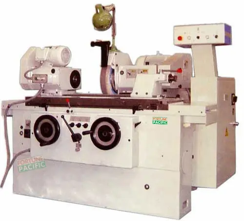
Descubra a retífica cilíndrica de precisão CG200E e CG320E da Fortune Pacific, também conhecida como máquina de retificar externa ou maquina de acabamento para eixos. Essas retificadoras cilíndricas universais são projetadas para usinagem de alta precisão de superfícies externas cilíndricas, cônicas e de pequenos ressaltos em peças como eixos, pinos, virabrequins (árvores de manivelas) e componentes de transmissão. Oferecem centro padrão de 500mm ou 1000mm, diâmetro máximo de retificação de 200mm ou 320mm, e velocidade do fuso de trabalho variável entre 50-500 rpm. Sua estrutura robusta em ferro fundido garante rigidez e amortecimento de vibrações excepcionais, enquanto o avanço da mesa e o posicionamento do cabeçote são controlados por servo motores e fusos de esferas de alta precisão, assegurando repetibilidade e acabamento superficial superior. Componentes essenciais incluem o cabeçote fixo com morsa, contra ponta, unidade de rebolo motorizada com eixo próprio, mesa deslizante hidráulica e sistema de refrigeração. Ideais para oficinas de manutenção, ferramentarias e produção de pequenos lotes na indústria automotiva, aeroespacial e moldes, destacam-se pela facilidade de operação, manutenção simplificada (baixa manutenção), confiabilidade comprovada e excelente custo-benefício (custo-benefício atrativo) para retífica de precisão. Atendem requisitos rigorosos de concentricidade e tolerâncias dimensionais apertadas. Matukoy ang de-kalidad na CG200E at CG320E Cylindrical Grinding Machine mula sa Fortune Pacific, kilala rin bilang panggiling na pabilog para sa mga shaft o panghuling panggiling ng ehersisyo. Ang mga universal cylindrical grinder na ito ay idinisenyo para sa mataas na katumpakan ng paggiling sa panlabas na cylindrical, conical surface, at maliliit na shoulder ng mga piyesa tulad ng mga shaft, pin, crankshaft (ehersisyo), at transmission component. Nag-aalok ito ng karaniwang sentro na 500mm o 1000mm, maximum grinding diameter na 200mm o 320mm, at variable work spindle speed mula 50-500 rpm. Ang matibay nitong cast iron structure ay nagbibigay ng mahusay na katigasan at vibration damping, habang ang table feed at headstock positioning ay kinokontrol ng servo motor at high precision ball screw, tinitiyak ang mahusay na repeatability at surface finish. Kabilang sa mga pangunahing bahagi ang fixed headstock na may chuck, tailstock, motorized grinding wheel unit na may sariling spindle, hydraulic sliding table, at coolant system. Perpekto para sa maintenance shop, tool room, at small batch production sa automotive, aerospace, at mold industry, kilala sa kadalian ng paggamit, simplified maintenance (mababang maintenance cost), napatunayang pagiging maaasahan (matibay), at mahusay na value for money (abot-kayang presyo) para sa precision grinding. Natutugunan nito ang mahigpit na kinakailangan sa concentricity at masisikip na dimensional tolerance. Scopri le rettificatrici cilindriche universali di precisione CG200E e CG320E di Fortune Pacific, note anche come macchine per la rettifica esterna o macchine per la finitura degli alberi. Queste macchine per rettifica cilindrica sono progettate per la lavorazione ad alta precisione di superfici esterne cilindriche, coniche e con piccole spalle su pezzi come alberi, perni, alberi a gomiti (alberi motore) e componenti per trasmissioni. Offrono una distanza tra punte standard di 500mm o 1000mm, un diametro massimo rettificabile di 200mm o 320mm e una velocità variabile del mandrino da lavoro da 50 a 500 giri/min. La robusta struttura in ghisa garantisce rigidità e smorzamento delle vibrazioni eccezionali, mentre l'avanzamento del carrello e il posizionamento della testa sono controllati da motori servo e viti a ricircolo di sfere di alta precisione, assicurando ripetibilità e finitura superficiale superiore. Componenti chiave includono la testa fissa con mandrino, la contropunta, l'unità motore mola con mandrino autonomo, il carrello scorrevole idraulico e il sistema di raffreddamento. Ideali per officine di manutenzione, reparti utensili e produzione a piccoli lotti nell'industria automobilistica, aerospaziale e degli stampi, si distinguono per facilità d'uso, manutenzione semplificata (bassa manutenzione), affidabilità collaudata e ottimo rapporto qualità-prezzo (convenienza) per la rettifica di precisione. Soddisfano rigorosi requisiti di concentricità e tolleranze dimensionali strette. Yüksek hassasiyetli CG200E ve CG320E Silindirik Taşlama Tezgahı'nı keşfedin, Fortune Pacific'ten gelen bu üniversal silindir taşlama makinaları (mil taşlama makinası veya iş mili taşlama cihazı olarak da bilinir). Bu dış yüzey taşlama makineleri, miller, pimler, krank milleri (kranklar) ve transmisyon parçaları gibi iş parçalarının silindirik, konik yüzeylerinin ve küçük step bölgelerinin hassas taşlanması için tasarlanmıştır. Standart 500mm veya 1000mm taşlama boyu, 200mm veya 320mm maksimum taşlama çapı ve 50-500 dev/dak arasında değişen iş mili hızı sunar. Güçlü dökme demir gövde, mükemmel rijitlik ve titreşim sönümleme sağlarken; tabla ilerlemesi ve ana mil konumlandırması servo motorlar ve yüksek hassasiyetli bilyalı vidalar ile kontrol edilir, üstün tekrarlanabilirlik ve yüzey kalitesi garanti eder. Temel bileşenler arasında ayna (pense) bulunan sabit ana mil ünitesi, puntalar, kendi miline sahip motorlu taşlama tekerleği ünitesi, hidrolik kayan tabla ve soğutma sistemi yer alır. Otomotiv, havacılık ve kalıp endüstrilerindeki bakım atölyeleri, takım odaları ve küçük seri üretim için idealdir. Kullanım kolaylığı, basit bakım (düşük bakım maliyeti), kanıtlanmış güvenilirlik (sağlam yapı) ve hassas taşlama için mükemmel fiyat/performans oranı (uygun fiyatlı çözüm) ile öne çıkar. Sıkı konsantrisite ve boyutsal tolerans gereksinimlerini karşılar. Découvrez la rectifieuse cylindrique universelle de précision CG200E et CG320E de Fortune Pacific, également connue sous le nom de machine à rectifier les surfaces extérieures ou rectifieuse pour arbres. Ces machines-outils sont conçues pour la rectification de haute précision de surfaces cylindriques, coniques et de petites épaulements sur des pièces comme des arbres, des axes, des vilebrequins et des composants de transmission. Elles offrent une distance entre pointes standard de 500mm ou 1000mm, un diamètre maximum de rectification de 200mm ou 320mm, et une vitesse variable de broche porte-pièce réglable de 50 à 500 tr/min. Leur structure robuste en fonte assure une rigidité exceptionnelle et un amorti des vibrations, tandis que l'avance de la table et le positionnement de la poupée fixe sont commandés par moteurs asservis et vis à billes de haute précision, garantissant une répétabilité parfaite et une superbe finition de surface. Les composants principaux incluent la poupée fixe avec mandrin (pince), la contre-pointe, l'unité porte-meule motorisée avec broche indépendante, la table coulissante hydraulique et le système de lubro-refroidissement. Idéales pour les ateliers de maintenance, les outils rooms et la production en petites séries dans les secteurs automobile, aérospatial et de la moulistérie, elles se distinguent par leur facilité d'utilisation, leur maintenance simplifiée (faible coût de maintenance), leur fiabilité éprouvée et leur excellent rapport qualité-prix (solution économique) pour la rectification de précision. Elles répondent aux exigences strictes de concentricité et de tolérances dimensionnelles serrées. اكتشف ماكينة تجليخ اسطواني CG200E وCG320E عالية الدقة من فورتشن باسيفيك، والمعروفة أيضًا باسم ماكينة التجليخ الخارجي أو مخرطة تجليخ الأعمدة. صممت هذه الماكينة العالمية للتجليخ الاسطواني لتقديم دقة فائقة في تجليخ الأسطح الخارجية الأسطوانية والمخروطية والكتف الصغير على قطع العمل مثل الأعمدة والدبابيس وعمود المرفق (الكرنك) ومكونات ناقل الحركة. توفر مسافة مركزية قياسية 500 مم أو 1000 مم، وقطر تجليخ أقصى 200 مم أو 320 مم، وسرعة متغيرة لعمود المشغولة من 50 إلى 500 دورة/دقيقة. يضمن هيكلها المصنوع من الحديد الزهر متانة استثنائية وتخميد للاهتزازات، بينما يتم التحكم في تغذية الطاولة وتحديد موضع رأسية الماكينة بواسطة محركات سيرفو ومسامير كروية عالية الدقة، مما يضمن تكرارية ممتازة وجودة سطح فائقة. تشمل المكونات الرئيسية الرأس الثابت مع ظرف التثبيت، الرأس المتحرك، وحدة عجلة التجليخ المزودة بمحرك خاص بها، طاولة انزلاق هيدروليكية، ونظام تبريد. مثالية لورش الصيانة وقوالب الأدوات والإنتاج بكميات صغيرة في صناعات السيارات والفضاء والقوالب، تتميز بسهولة الاستخدام، وصيانة مبسطة (تكلفة صيانة منخفضة)، وموثوقية مثبتة، وقيمة متميزة مقابل السعر (حل اقتصادي) لأعمال التجليخ الدقيق. تلبي متطلبات دقة التوافق المحوري والتسامحات الأبعاد الضيقة. Entdecken Sie die hochpräzisen Universal-Rundschleifmaschinen CG200E und CG320E von Fortune Pacific, auch bekannt als Außenschleifmaschine oder Wellenschleifmaschine. Diese Rundschleifmaschinen sind für das Hochpräzisionsschleifen zylindrischer, konischer Außenflächen und kleiner Schultern an Werkstücken wie Wellen, Stiften, Kurbelwellen (Kurbeln) und Getriebekomponenten konzipiert. Sie bieten eine Standard-Spannlänge von 500mm oder 1000mm, einen maximalen Schleifdurchmesser von 200mm oder 320mm und eine variable Arbeitsspindeldrehzahl zwischen 50-500 U/min. Das robuste Gusseisen-Gehäuse garantiert außergewöhnliche Steifigkeit und Schwingungsdämpfung, während der Tischvorschub und die Spindelstockpositionierung durch Servomotoren und hochpräzise Kugelgewindetriebe gesteuert werden, was hervorragende Wiederholgenauigkeit und Oberflächengüte sichert. Wichtige Komponenten umfassen den Festspindelstock mit Spannfutter, den Reitstock, das motorisierte Schleifspindelaggregat mit eigener Spindel, den hydraulischen Schlittentisch und das Kühlschmiermittel-System. Ideal für Instandhaltungswerkstätten, Werkzeugbaubetriebe und Kleinserienfertigung in der Automobil-, Luftfahrt- und Formenbauindustrie, überzeugen sie durch einfache Bedienung, wartungsarmen Betrieb (niedrige Wartungskosten), bewährte Zuverlässigkeit und hervorragendes Preis-Leistungs-Verhältnis (kosteneffiziente Lösung) für das Präzisionsschleifen. Sie erfüllen strenge Anforderungen an Rundlaufgenauigkeit und enge Maßtoleranzen. Ontdek de hoogwaardige universele cilindrische slijpmachines CG200E en CG320E van Fortune Pacific, ook wel bekend als oppervlakteslijpmachines of asafdraaimachines. Deze precisie cilindergrinders zijn ontworpen voor het nauwkeurig slijpen van cilindrische, conische buitenoppervlakken en kleine schouders op werkstukken zoals assen, pennen, krukassen (krukken) en transmissie-onderdelen. Ze bieden een standaard centerafstand van 500mm of 1000mm, een maximaal slijpdiameter van 200mm of 320mm, en een variabele werkspindelsnelheid tussen 50-500 omw/min. Het robuuste gietijzeren frame zorgt voor uitstekende stijfheid en trillingsdemping, terwijl de tafelvoeding en spindelkop positionering worden geregeld door servomotoren en hoogprecisie kogelomloopspindels, wat een uitstekende herhaalbaarheid en oppervlaktekwaliteit garandeert. Belangrijke onderdelen zijn de vaste spindelkop met drieklauw, losse kop, gemotoriseerd slijpspindelaggregaat met eigen spil, hydraulisch verschuifbare tafel en koelsmeersysteem. Ideaal voor onderhoudswerkplaatsen, gereedschapsmakerijen en kleine serieproductie in de auto-, luchtvaart- en matrijzenindustrie, vallen ze op door gebruiksvriendelijkheid, eenvoudig onderhoud (lage onderhoudskosten), bewezen betrouwbaarheid en uitstekende prijs-kwaliteitverhouding (rendabele oplossing) voor precisieslijpen. Ze voldoen aan strenge concentriteitseisen en nauwe maattoleranties. Poznaj wysokiej klasy uniwersalne szlifierki do wałków CG200E i CG320E marki Fortune Pacific, znane również jako szlifierki do płaszczyzn zewnętrznych lub szlifierki do obróbki czopów. Te precyzyjne szlifierki cylindryczne zaprojektowano do dokładnej obróbki powierzchni zewnętrznych cylindrycznych, stożkowych i małych stopni na elementach takich jak wały, czopy, wały korbowe (korby) oraz części przekładni. Oferują standardowy rozstaw kłów 500mm lub 1000mm, maksymalną średnicę szlifowania 200mm lub 320mm oraz zmienną prędkość wrzeciona przedmiotowego w zakresie 50-500 obr/min. Solidna konstrukcja żeliwna zapewnia wyjątkową sztywność i tłumienie drgań, podczas gdy posuw stołu i pozycjonowanie wrzeciona przedmiotowego sterowane są silnikami serwo i precyzyjnymi śrubami kulowymi, gwarantując doskonałą powtarzalność i jakość powierzchni. Kluczowe komponenty obejmują stałą głowicę wrzeciona z uchwytem, ruchomy wrzeciono, zespół szlifierski z własnym silnikiem, hydrauliczny stół przesuwny oraz układ chłodzenia. Idealne do warsztatów serwisowych, narzędziowni i małoseryjnej produkcji w przemyśle motoryzacyjnym, lotniczym i form, wyróżniają się łatwością obsługi, prostą konserwacją (niskie koszty utrzymania), sprawdzoną niezawodnością i doskonałym stosunkiem jakości do ceny (ekonomiczne rozwiązanie) do precyzyjnego szlifowania. Spełniają rygorystyczne wymagania współosiowości i wąskich tolerancji wymiarowych. Descoperiți mașinile de rectificat cilindrică universală de precizie CG200E și CG320E de la Fortune Pacific, cunoscute și sub denumirea de mașină de rectificat exterior sau mașină de finisat arbori. Aceste mașini de rectificat cilindrică sunt concepute pentru rectificarea de înaltă precizie a suprafețelor exterioare cilindrice, conice și a umerilor mici pe piese cum ar fi arbori, pini, arbori cotiți și componente de transmisie. Oferă distanță între vârfuri standard de 500mm sau 1000mm, diametru maxim de rectificat de 200mm sau 320mm și viteză variabilă a axului piesei între 50-500 rot/min. Construcția robustă din fontă asigură rigiditate și amortizare a vibrațiilor excepționale, iar avansul mesei și poziționarea capului port-piesă sunt controlate de motoare servo și șuruburi cu bile de înaltă precizie, garantând repetabilitate și calitate superioară a suprafeței finisate. Componentele principale includ capul fix cu universală (mandrină), contrapunctul, unitatea motorizată a roții abrazive cu ax propriu, masa glisantă hidraulică și sistemul de răcire. Ideale pentru atelierele de întreținere, secțiile scule și producția în serii mici din industria auto, aerospațială și a matrițelor, se remarcă prin ușurința în utilizare, întreținere simplificată (costuri reduse de întreținere), fiabilitate dovedită și raport excelent calitate-preț (soluție rentabilă) pentru rectificarea de precizie. Îndeplinesc cerințe stricte de concentricitate și toleranțe dimensionale strânse.