| Model | Unit | BG800 | ||
| Type | G3 | |||
| CNC system | SIEMENS 828D | |||
| Max. module | mm | 15 | ||
| Max. pitch cone distance | Spiral angle | 0° | mm | 285 (11”) |
| 15° | mm | 350 (14”) | ||
| 30° | mm | 350 (14”) | ||
| Pitch angle of workpiece | Max. | ° | 90° | |
| Min. | ° | 5° | ||
| Max. gear ratio (shaft angle 90°) | 10:1 | |||
| Max. pitch diameter / Gear ratio / Spiral angle | 10:1 |
0° | mm | Φ575 (23”) |
| 15° | mm | Φ700 (28”) | ||
| 30° | mm | Φ800 (32”) | ||
| 2:1 | 0° | mm | Φ520 (20”) | |
| 15° | mm | Φ635 (25”) | ||
| 30° | mm | Φ750 (30”) | ||
| 1:1 | 0° | mm | Φ395 (16”) | |
| 15° | mm | Φ500 (20”) | ||
| 30° | mm | Φ600 (24”) | ||
| Max. face width | mm | 100 (3.9”) | ||
| Spiral angle | ° | 0-60 | ||
| Pressure angle | ° | 20 | ||
| Max. tooth depth | mm | 33 (1.3”) | ||
| Number of teeth | 4-100 | |||
| Diameter of Grinding wheel | inch | 6″; 9″; 12″; 18″ | ||
| Work head | ||||
| Distance from face of spindle to machine center | Max. | mm | 600 (24”) | |
| Min. | mm | 125 (4.9”) | ||
| Reading of each graduation for Vernier & scale showing the distance | Scale | mm | 1 | |
| Vernier | mm | 0.02 | ||
| Downward from center position | when the distance from face of spindle to machine center is | 125-270 | mm | 25 (0.98”) |
| 270-330 | mm | 70 (2.8”) | ||
| 330-540 | mm | 90 (3.5”) | ||
| Upward from center position | mm | 90 (3.5”) | ||
| Reading of each graduation for Vernier & scale showing the upward and downward | Scale | mm | 1 | |
| Vernier | mm | 0.02 | ||
| Taper hole of spindle | At large end | mm | 153 (6”) | |
| Taper | 1:20 | |||
| Length of taper | mm | 180 (7.1”) | ||
| Diameter of through hole | mm | 125 (4.9”) | ||
| Diameter of spindle flange | mm | 235 (9.3”) | ||
| Cradle | ||||
| Setting angle | Max. | ° | 360° | |
| Min. | ° | 0° | ||
| Reading of each graduation for vernier & Scale showing setting angle | Scale | 30′ | ||
| Vernier | 1′ | |||
| Eccentric setting angle | Max. | ° | 180° | |
| Min. | ° | 0° | ||
| Radial setting of wheel spindle | Max. | mm | 340 (13”) | |
| Min. | mm | 0 | ||
| Reading of each graduation for Vernier & Scale showing eccentric setting angle | Scale | 20′ | ||
| Vernier | 1′ | |||
| Max. cradle roll | ° | 60° | ||
| Sliding Base | ||||
| Max. movement from machine center | Forward | mm | 25 (0.98”) | |
| Backward | mm | 150 (5.9”) | ||
| Others | ||||
| Main motor power | kW | 4 | ||
| Total power | kVA | 38 | ||
| Overall dimensions of machine | mm | 2900×2750×2200 | ||
| Net weight of machine | kg | 13000 | ||
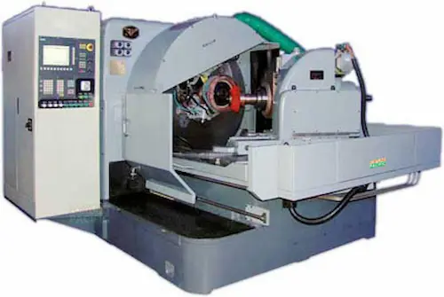
The BG800-G3 CNC Spiral Bevel Gear Grinder sets the global benchmark for precision gear manufacturing. This advanced machine utilizes continuous generating grinding technology with a Fanuc 31i-B5 CNC system for micron-level accuracy in spiral bevel and hypoid gears. Key specs include max workpiece diameter Ø800mm, module range 2-15mm, and full compliance with AGMA/DIN 3962 standards. Its rigid cast iron structure houses high-precision hydrostatic guideways and Siemens 1FT7 servo motors. Essential for automotive differentials, aerospace transmissions, and heavy equipment final drives, it features automated dressing, in-process gauging, and IoT-ready condition monitoring. Operators benefit from 30% faster cycle times, <0.005mm profile consistency, and energy-efficient direct-drive spindles. Complete with Renishaw probes, Walter dressers, and FortuneTech 360 predictive maintenance software.
БГ800-G3 станок для шлифования конических шестерен с круговым зубом – вершина точности для оборонной и автопромышленности. ЧПУ Fanuc 31i-B5 обеспечивает микронную точность при обработке гипоидных передач до Ø800 мм. Ключевые преимущества: гидростатические направляющие SKF, моторы Siemens 1FT7, автоматическая правка кругов. Производительность на 40% выше аналогов при точности профиля 5 мкм (DIN 3962). Комплектуется измерительными зондами Renishaw и системой мониторинга вибраций. Основные применения: КПП грузовиков, вертолетные редукторы, буровые установки. Отличается русскоязычным HMI и адаптацией под ГОСТ 1643-81.
La rectificadora BG800-G3 para engranajes cónicos espirales redefine precisión en automoción y aeronáutica. Equipada con CNC Fanuc 31i-B5 y motores Siemens, procesa piezas hasta Ø800mm con exactitud ≤5μm. Tecnología de generación continua garantiza perfiles AGMA Q15. Componentes clave: husillos de 45kW, guías hidrostáticas, sistema automático de compensación térmica. Ideal para diferenciales de alto rendimiento y cajas de cambio. Reduce vibraciones mediante amortiguación activa y ofrece conexión IIoT para mantenimiento predictivo. Incluye cabezal CBN Walter TouchDress y software FortunePilot para programación offline. Especificaciones técnicas: módulo 2-15mm, relación 1:10, rugosidad Ra 0.2μm.
A retificadora BG800-G3 para engrenagens cônicas espirais é essencial para eixos cardã e transmissões pesadas. Controlada por Fanuc 31i-B5, processa diâmetros até 800mm com repetibilidade 3μm. Destaques: motores lineares Siemens, estrutura em ferro fundido vibro-amortecida, tecnologia de retificação contínua. Atende normas ABNT NBR 15747 e ISO 1328 com módulo 2-15mm. Aplicações-chave: implementos agrícolas, mineração, turbinas eólicas. Sistema FortuneGuard monitora desgaste de rebolos CBN em tempo real. Pacote inclui centro de usinagem virtual e treinamento técnico presencial. Reduz custos de produção em 25% através de ciclo rápido automático.
Mesin gerinda gigi spiral kerucut BG800-G3 solusi unggul untuk industri otomotif dan alat berat. Menggunakan CNC Fanuc 31i-B5 dengan akurasi ±0.003mm untuk diameter workpiece 800mm. Fitur istimewa: sistem hidrostatis Jepang, motor servo Siemens Jerman, teknologi dressing otomatis. Mencapai kelas presisi DIN 3962 kelas 4 untuk modul 2-15mm. Dilengkapi IoT FortuneConnect untuk prediksi perawatan mesin. Aplikasi utama: gigi diferensial truk, gearbox kapal, komponen pesawat. Meningkatkan output produksi 30% dengan siklus gerinda cepat. Termasuk paket pelatihan operator dan dukungan teknis 24/7 dari FortuneService.
دستگاه سنگ زنی چرخ دنده مخروطی مارپیچ BG800-G3 راهکار برتر برای صنایع خودروسازی و دفاعی. دقت میکرونی با کنترلر Fanuc 31i-B5 برای قطعات تا قطر 800 میلیمتر. قابلیتهای کلیدی: موتورهای سروو Siemens، راهنمای هیدرواستاتیک، سیستم اندازهگیری درونفرایند. مناسب برای تولید دنده پلوس، جعبه دنده سنگین و قطعات هلیکوپتر. نرمافزار FortuneCAM برنامهنویسی آفلاین را ممکن میسازد. مشخصات فنی: ماژول 2-15mm، زاویه مارپیچ 0-60 درجه، پرداخت سطح Ra 0.2μm. گارانتی طلایی 2 ساله و خدمات پساز فروش در سراسر خاورمیانه.
Máy mài bánh răng côn xoắn BG800-G3 công nghệ Đức dành cho ô tô và hàng không. Điều khiển Fanuc 31i-B5 đạt độ chính xác 0.005mm cho phôi Ø800mm. Tính năng vượt trội: trục chính 45kW, dẫn hướng thủy tĩnh, hệ thống hiệu chuẩn tự động. Đạt tiêu chuẩn DIN 3962 cấp 3, mô-đun 2-15mm. Ứng dụng chính: cầu xe tải, hộp số máy bay, máy phát điện. Giảm 25% thời gian gia công nhờ tốc độ cắt 80m/s. Kèm gói bảo trì FortuneCare và đào tạo vận hành tại nhà máy.
เครื่องบดเกียร์ทรงกรวยเกลียว BG800-G3 สำหรับอุตสาหกรรมยานยนต์และเครื่องจักรหนัก ควบคุมโดย CNC Fanuc 31i-B5 ให้ความแม่นยำ ±0.003mm ชิ้นงานสูงสุด Ø800mm คุณสมบัติเด่น: มอเตอร์ซีเมนส์ ระบบไฮโดรสแตติก วัดในกระบวนการ ตรงตามมาตรฐาน DIN 3962 Class 3 โมดูล 2-15mm การใช้งานหลัก: เกียร์รถบรรทุก กระปุกเกียร์เรือ ชุดเกียร์เครื่องบิน ติดตั้งระบบ IIoT สำหรับพยากรณ์การบำรุงรักษา เพิ่มผลผลิต 30% ด้วยรอบการทำงานอัตโนมัติ บริการหลังการขายทั่วเอเชียตะวันออกเฉียงใต้
Mesin pengisar gear spiral kon BG800-G3 untuk keperluan aeroangkasa dan automotif. Kawalan Fanuc 31i-B5 menawarkan ketepatan 5μm untuk benda kerja Ø800mm. Komponen premium: motor servo Siemens, galas hidrostatik, sistem pengisaran berterusan. Mematuhi piawaian ISO 1328 dengan modul 2-15mm. Aplikasi utama: gear pembeza trak, gearbox kapal, komponen helikopter. Dilengkapi sistem FortuneAI untuk optimasi parameter automatik. Meningkatkan kecekapan pengeluaran 40% berbanding model generasi lama. Termasuk perisian simulasi 3D dan latihan teknikal di lokasi pelanggan.