| Model | Unit | RTM600 |
| Type | C3 | |
| CNC system | SIEMENS 840D | |
| Max. outside diameter of gear | mm | 600 |
| Max. outside diameter of pinion | mm | 254 |
| Max offset | mm | ±76 |
| Distance from gear spindle nose to pinion spindle axis | mm | 89-270 |
| Distance from pinion spindle nose to gear spindle axis | mm | 165-360 |
| Pinion spindle | ||
| Diameter of spindle hole at large end | mm | 100 |
| Taper | 1:20 | |
| Taper depth | mm | 80 |
| Diameter of through hole | mm | 96 |
| Gear spindle | ||
| Diameter of spindle hole at large end | mm | 60 |
| Taper | 1:20 | |
| Taper depth | mm | 24 |
| Diameter of through hole | mm | 50 |
| Braking torque | Nm | 2-50 |
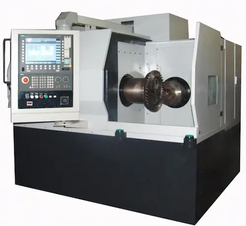
RTM600-C3 Bevel Gear Rolling Testing Machine delivers unmatched precision in gear quality control. This robust machine simulates real-world operating conditions to meticulously inspect bevel gear sets (straight, spiral, hypoid) for noise, contact pattern, backlash, and transmission errors up to 600mm in diameter. Engineered for demanding industries like automotive, truck, aerospace, agriculture, and heavy machinery, its core components include rigid mechanical structure, high-precision servo drive system, industrial PC control, and advanced torque/speed sensors. Key advantages are exceptional repeatability (C3 grade accuracy per DIN standards), user-friendly WinOS software with comprehensive data analysis/reporting, high testing efficiency, and unparalleled reliability for critical gear validation. It ensures gears meet stringent quality standards for smooth, quiet, and durable performance. Crucial parameters include max test diameter, torque capacity, speed range, and compliance with DIN 3975/ISO 17485. Global users prioritize its accuracy, data integrity, and ability to detect micro-geometry defects preventing costly field failures.
Станок для прикатки конических шестерен RTM600-C3 (Машина для проверки зацепления конических пар) — эталон надежности в контроле качества зубчатых передач. Эта мощная установка воспроизводит реальные условия эксплуатации для тщательной проверки конических передач (прямозубых, спиральных, гипоидных) диаметром до 600 мм на шум, пятно контакта, боковой зазор и кинематическую погрешность. Незаменима в автомобилестроении, авиакосмической отрасли, сельхозмашиностроении и тяжелой промышленности. Ключевые узлы: усиленная станина, высокоточный сервопривод, промышленный ПК с ОС Windows, прецизионные датчики момента и скорости. Преимущества: высочайшая повторяемость результатов (класс точности С3 по DIN), интуитивное ПО с анализом данных и отчетами, высокая производительность прикатки, исключительная надежность для ответственных проверок. Обеспечивает соответствие шестерен строгим стандартам DIN 3975/ISO 17485 на бесшумность и долговечность. Ключевые параметры: макс. диаметр проверки, момент нагрузки, диапазон скоростей. Пользователи ценят точность, достоверность данных и выявление микрогеометрии зубьев для предотвращения дорогостоящих поломок.
La Máquina de Prueba de Rodadura para Engranajes Cónicos RTM600-C3 es la solución definitiva para el control de calidad de engranajes. Este robusto equipo simula condiciones reales de funcionamiento para inspeccionar minuciosamente juegos de engranajes cónicos (rectos, espirales, hipoides) de hasta 600mm de diámetro, evaluando ruido, patrón de contacto, juego lateral y errores de transmisión. Diseñada para la industria automotriz, aeroespacial, agrícola y maquinaria pesada, sus componentes principales incluyen estructura mecánica rígida, sistema servoaccionado de alta precisión, PC industrial con software bajo Windows y sensores avanzados de par/velocidad. Ofrece repetibilidad excepcional (precisión grado C3 según normas DIN), software intuitivo con análisis de datos e informes detallados, alta eficiencia y fiabilidad inigualable para validación crítica de engranajes. Garantiza el cumplimiento de estándares rigurosos DIN 3975/ISO 17485 para un funcionamiento silencioso y duradero. Parámetros clave: diámetro máximo de prueba, capacidad de par, rango de velocidades. Los usuarios globales priorizan su exactitud, integridad de datos y capacidad para detectar defectos de microgeometría evitando fallos costosos.
A Máquina de Teste de Rolamento para Engrenagens Cônicas RTM600-C3 oferece precisão máxima no controle de qualidade de engrenagens. Este equipamento robusto simula condições reais de operação para inspecionar minuciosamente conjuntos de engrenagens cônicas (diretas, espirais, hipoides) com até 600mm de diâmetro, verificando ruído, padrão de contato, folga e erros de transmissão. Essencial para indústrias automotiva, aeroespacial, agrícola e de máquinas pesadas, seus componentes principais incluem estrutura rígida, sistema servoacionado de alta precisão, PC industrial com software Windows e sensores avançados de torque/velocidade. Vantagens: repetibilidade excepcional (classe de precisão C3 conforme normas DIN), software amigável com análise de dados e relatórios, alta produtividade no teste e confiabilidade incomparável para validação crítica de engrenagens. Garante conformidade com rigorosos padrões DIN 3975/ISO 17485 para desempenho suave e durável. Parâmetros cruciais: diâmetro máximo de teste, capacidade de torque, faixa de velocidades. Usuários globais valorizam sua precisão, integridade dos dados e capacidade de detectar microdefeitos na geometria dos dentes, prevenindo falhas dispendiosas.
Mesin Uji Rolling Gear Bevel RTM600-C3 memberikan solusi presisi tinggi untuk kontrol kualitas gear. Mesin tangguh ini mensimulasikan kondisi operasi nyata guna memeriksa set gear bevel (lurus, spiral, hypoid) hingga diameter 600mm secara teliti, menguji kebisingan, pola kontak, backlash, dan kesalahan transmisi. Dirancang untuk industri otomotif, penerbangan, pertanian, dan alat berat. Komponen utama: struktur mekanik kokoh, sistem penggerak servo presisi tinggi, PC industri dengan software berbasis Windows, serta sensor torsi/kecepatan mutakhir. Keunggulan: pengulangan hasil uji luar biasa (akurasi kelas C3 standar DIN), software ramah pengguna dengan analisis data/laporan komprehensif, efisiensi pengujian tinggi, dan keandalan tak tertandingi untuk validasi gear kritis. Memastikan gear memenuhi standar ketat DIN 3975/ISO 17485 untuk kinerja halus, senyap, dan tahan lama. Parameter penting: diameter uji maks, kapasitas torsi, rentang kecepatan. Pengguna global memprioritaskan akurasi, integritas data, dan kemampuannya mendeteksi cacat mikro-geometri gigi untuk mencegah kegagalan lapangan yang mahal.
دستگاه تست غلتشی چرخ دنده مخروطی RTM600-C3 (ماشین تست درگیری چرخدنده های مخروطی) ابزار برتر کنترل کیفیت دنده با دقت بینظیر. این دستگاه قدرتمند شرایط عملیاتی واقعی را شبیهسازی میکند تا مجموعه چرخدندههای مخروطی (ساده، مارپیچ، هایپوئید) تا قطر 600 میلیمتر را با دقت بالا برای نویز، الگوی تماس، لقی جانبی (بک لش) و خطاهای انتقال بررسی کند. حیاتی برای صنایع خودروسازی، کامیونسازی، هوافضا، کشاورزی و ماشینآلات سنگین. اجزای کلیدی: ساختار مکانیکی مستحکم، سیستم محرک سروو با دقت بالا، کامپیوتر صنعتی با نرمافزار تحت ویندوز، حسگرهای پیشرفته گشتاور/سرعت. مزایا: تکرارپذیری استثنایی (دقت درجه C3 مطابق استانداردهای DIN)، نرمافزار کاربرپسند با تحلیل داده و گزارشگیری جامع، بازدهی تست بالا و قابلیت اطمینان منحصر به فرد برای اعتبارسنجی چرخدندههای حساس. تضمین کننده انطباق با استانداردهای سختگیرانه DIN 3975/ISO 17485 برای عملکردی نرم، بیصدا و بادوام. پارامترهای حیاتی: حداکثر قطر تست، ظرفیت گشتاور، محدوده سرعت. کاربران جهانی دقت بالا، صحت دادهها و توانایی آن در آشکارسازی عیوب ریز هندسی دندانه برای جلوگیری از خرابیهای پرهزینه در میدان را ارج مینهند.
Máy Kiểm Tra Bánh Răng Côn RTM600-C3 (Máy Chạy Rà Bánh Răng Côn) đặt tiêu chuẩn cao về kiểm soát chất lượng bánh răng. Thiết bị mạnh mẽ này mô phỏng điều kiện vận hành thực tế để kiểm tra kỹ lưỡng bộ bánh răng côn (răng thẳng, răng xoắn, hypoid) đường kính lên tới 600mm về độ ồn, vết tiếp xúc, độ hở hướng trục và sai số truyền động. Thiết yếu cho ngành ô tô, hàng không vũ trụ, nông nghiệp và máy móc hạng nặng. Cấu thành chính: kết cấu cơ khí vững chắc, hệ thống truyền động servo chính xác cao, máy tính công nghiệp chạy phần mềm Windows, cảm biến mô-men/tốc độ tiên tiến. Ưu điểm vượt trội: độ lặp lại kết quả cực cao (độ chính xác cấp C3 theo tiêu chuẩn DIN), phần mềm thân thiện với phân tích dữ liệu và báo cáo toàn diện, hiệu suất kiểm tra cao và độ tin cậy tuyệt đối cho việc đánh giá bánh răng quan trọng. Đảm bảo bánh răng đạt chuẩn DIN 3975/ISO 17485 khắt khe về vận hành êm ái, ít ồn và bền bỉ. Thông số kỹ thuật quan trọng: đường kính kiểm tra tối đa, công suất mô-men, dải tốc độ. Người dùng toàn cầu đánh giá cao độ chính xác, tính toàn vẹn dữ liệu và khả năng phát hiện khuyết tật vi hình dạng răng, ngăn ngừa hư hỏng tốn kém ngoài thực tế.
เครื่องทดสอบการทำงานเกียร์แบบ Bevel RTM600-C3 (เครื่องทดสอบการสัมผัสเกียร์แบบเกลียว) ให้ความแม่นยำสูงสุดในการควบคุมคุณภาพเกียร์ เครื่องมืออันทนทานนี้จำลองสภาวะการทำงานจริงเพื่อตรวจสอบชุดเกียร์ Bevel (ตรง, เฮลิคอล, ไฮปอยด์) ขนาดเส้นผ่านศูนย์กลางสูงสุด 600 มม. อย่างละเอียด ครอบคลุมการทดสอบเสียงรบกวน, รูปแบบการสัมผัสฟันเกียร์, การหลวมด้านข้าง และข้อผิดพลาดในการส่งกำลัง ออกแบบมาสำหรับอุตสาหกรรมยานยนต์, การบินและอวกาศ, เกษตรกรรม และเครื่องจักรหนัก องค์ประกอบหลักประกอบด้วยโครงสร้างกลไกที่แข็งแกร่ง, ระบบขับเคลื่อนเซอร์โวความแม่นยำสูง, คอมพิวเตอร์อุตสาหกรรมพร้อมซอฟต์แวร์ Windows และเซ็นเซอร์วัดแรงบิด/ความเร็วขั้นสูง ข้อได้เปรียบหลัก: ความแม่นยำและความสม่ำเสมอของผลการทดสอบ (เกรด C3 ตามมาตรฐาน DIN), ซอฟต์แวร์ใช้งานง่ายพร้อมการวิเคราะห์ข้อมูลและรายงานแบบครบวงจร, ประสิทธิภาพการทดสอบสูง และความน่าเชื่อถือเหนือระดับสำหรับการตรวจสอบเกียร์ที่สำคัญ มั่นใจได้ว่าเกียร์ตรงตามมาตรฐาน DIN 3975/ISO 17485 ที่เข้มงวดเพื่อประสิทธิภาพการทำงานที่เงียบ, เรียบเนียน และทนยาวนาน พารามิเตอร์สำคัญ: ขนาดเกียร์สูงสุดที่ทดสอบได้, ความสามารถในการรับแรงบิด, ช่วงความเร็ว ผู้ใช้งานทั่วโลกให้ความสำคัญกับความเที่ยงตรง, ความสมบูรณ์ของข้อมูล และความสามารถในการตรวจจับข้อบกพร่องขนาดเล็กของฟันเกียร์ เพื่อป้องกันความเสียหายที่มีค่าใช้จ่ายสูง
Mesin Ujian Rolling Gear Bevel RTM600-C3 menawarkan ketepatan tertinggi dalam kawalan kualiti gear. Mesin kukuh ini mensimulasikan keadaan operasi sebenar untuk memeriksa set gear bevel (lurus, spiral, hipoid) sehingga diameter 600mm dengan teliti, menguji bunyi, corak sentuhan, kelonggaran dan ralat penghantaran. Direka untuk industri automotif, aeroangkasa, pertanian dan jentera berat. Komponen utama: struktur mekanikal teguh, sistem pacuan servo ketepatan tinggi, PC perindustrian dengan perisian Windows, serta sensor tork/halaju termaju. Kelebihan: kebolehulangan keputusan ujian yang luar biasa (ketepatan gred C3 mengikut piawaian DIN), perisian mesra pengguna dengan analisis data/laporan komprehensif, kecekapan ujian tinggi dan kebolehpercayaan unggul untuk pengesahan gear kritikal. Memastikan gear memenuhi piawaian ketat DIN 3975/ISO 17485 untuk prestasi lancar, senyap dan tahan lama. Parameter utama: diameter ujian maks, kapasiti tork, julat halaju. Pengguna global mengutamakan ketepatannya, integriti data serta keupayaan mengesan kecacatan mikro-geometri gigi bagi mencegah kegagalan lapangan yang mahal.
A máquina de teste de rolagem de engrenagens cônicas RTM600-C3, também conhecida como "testadora de engrenagens cônicas" ou "roladora para engrenagem cônica", é essencial para controle de qualidade na indústria automotiva e de transmissões. Este equipamento de medição de precisão avalia o contato do flanco do dente, ruído e padrão de engrenamento através de rotação simulada sob carga controlada. Fabricada com componentes de alta resistência como base rígida em ferro fundido, eixo principal de alta precisão e sistema de carga pneumática, garante confiabilidade operacional (confiabilidade de máquina industrial). Parâmetros técnicos incluem diâmetro máximo da engrenagem de 600mm, módulo 1-10mm, velocidade de rotação ajustável e medição precisa do ângulo de hélice. Sua aplicação abrange fabricantes de engrenagens cônicas para eixos cardã, diferenciais e sistemas de direção. Vantagens principais: alta eficiência de teste (reduz tempo de inspeção), excelente repetibilidade, operação simplificada via HMI e geração automática de relatórios de conformidade. Ideal para quem busca "equipamento para teste de qualidade de engrenagens" ou "máquina inspeção engrenagem cônica".
Ang RTM600-C3 Bevel Gear Rolling Test Machine o "Bevel Gear Roll Tester" ay pangunahing kagamitan sa pag-inspeksyon ng kalidad para sa mga bevel gear na ginagamit sa sasakyan, transmission, at heavy machinery. Tinatawag din itong "Pangsubok ng Engranasyong Kono" o "Makina ng Pag-roll ng Gear". Gumagana ito sa pamamagitan ng pag-ikot ng magkasalubong na gear sa ilalim ng kontroladong karga, sinusuri ang contact pattern ng ngipin, ingay, at smoothness ng engagement. Pangunahing komponente: matibay na cast iron base, high-precision spindle, adjustable tailstock, pneumatic loading system, at user-friendly control panel. Mga teknikal na parameter: maximum gear diameter na 600mm, module 1-10mm, at mataas na katumpakan ng pagsukat. Ginagamit ito ng mga tagagawa ng gear para matiyak ang "tumpak na pagkakabit ng bevel gear" at "maayos na operasyon", na nagbabawas sa mga defect at warranty claim. Pakinabang: mabilis na "pagsubok sa kalidad ng gear", automation, pag-record ng data, at pagtaas ng produktibidad. Mahalaga ito para sa pagpapanatili ng "mataas na standard ng produksyon" at paggawa ng "de-kalidad na mga piyesa ng sasakyan".
La macchina per prove di rullatura per ingranaggi conici RTM600-C3, nota anche come "controllore qualità ingranaggi conici" o "rullatrice per ingranaggi", è fondamentale per garantire la precisione di ingranamento in settori automobilistico e aerospaziale. Funziona simulando il movimento rotatorio sotto carico controllato, analizzando l'impronta di contatto, il rumore e la scorrevolezza (valutazione prestazioni ingranaggi). Dotata di struttura robusta in ghisa, mandrino ad alta precisione, controtestina regolabile e sistema di carico pneumatico. Specifiche tecniche: diametro massimo ingranaggio 600mm, modulo 1-10mm, velocità regolabile. Applicazioni chiave: produzione differenziali, giunti cardanici, riduttori industriali. Vantaggi principali: alta efficienza nei test di collaudo (riduzione tempi ispezione), affidabilità operativa, interfaccia utente intuitiva e generazione automatica report. Ideale per officine che cercano "controllo qualità automatizzato ingranaggi" o "macchinario test precisione conici", assicura "lavorazioni silenziose" e "durabilità componenti".
RTM600-C3 Konik Dişli Yuvarlanma Test Makinesi "Konik Dişli Kontrol Cihazı" veya "Dişli Test Presi" olarak da bilinir, otomotiv dişli kutusu ve şanzıman üreticileri için kritik kalite kontrol ekipmanıdır. Çalışma prensibi: kontrollü yük altında dişli çiftini döndürerek diş temas izi, gürültü seviyesi ve geçiş düzgünlüğünü (dişli performans analizi) test eder. Sağlam döküm demir gövde, yüksek hassasiyetli mil, ayarlanabilir punta ve pnömatik yükleme sistemine sahiptir. Teknik özellikler: maksimum 600mm dişli çapı, modül 1-10mm, yüksek tekrarlanabilirlik. Başlıca kullanım alanları: diferansiyel dişlileri, akslar, endüstriyel redüktörler. Avantajlar: "hızlı dişli test süreci", kullanım kolaylığı, veri kayıt özelliği ve "üretim verimliliği artışı". "Yüksek hassasiyetli konik dişli üretimi" için ideal olan bu makine, "imalat hatalarını azaltır" ve "vibrasyon testi" ile sessiz çalışan dişliler sağlar.
La machine d'essai de roulage pour engrenages coniques RTM600-C3, appelée aussi "contrôleur qualité engrenages" ou "rouleuse d'engrenages", est indispensable pour valider la géométrie des pignons coniques dans l'automobile et l'aéronautique. Principe : rotation simulée sous charge contrôlée analysant la portée dentaire, le bruit et la fluidité d'engrènement. Construction robuste en fonte, broche de précision, contre-pointe réglable et système de chargement pneumatique. Paramètres : diamètre max. engrenage 600mm, module 1-10mm, répétabilité élevée. Applications : fabrication d'engrenages pour différentiels, transmissions et réducteurs industriels. Avantages clés : "test rapide d'engrenage", automatisation des contrôles qualité, fiabilité "sans entretien" et génération de rapports. Solution optimale pour "vérification précision engrenage conique" ou "équipement contrôle qualité denture", assurant une "production sans défaut" et réduisant les coûts de non-qualité.
ماكينة اختبار تدوير التروس المخروطية RTM600-C3، المعروفة أيضًا باسم "جهاز فحص التروس المخروطية" أو "ماكينة دحرجة التروس"، هي معدات فحص جودة حاسمة لصناعات السيارات والطيران. مبدأ العمل: تدوير زوج الترس تحت حمل محكم لتحليل نمط التلامس، الضوضاء، وسلاسة الاشتغال (تحليل أداء الترس). المكونات: هيكل حديد زهر متين، محور عالي الدقة، رأس متحرك قابل للتعديل، ونظام تحميل هوائي. المواصفات: قطر ترس أقصى 600 مم، موديول 1-10 مم، دقة قياس عالية. التطبيقات الرئيسية: تصنيع تروس الديفرنسيال، صناديق التروس، ومخفضات السرعة الصناعية. المزايا: "كفاءة فحص التروس" عالية، موثوقية تشغيلية، واجهة تحكم بسيطة، وتقارير تلقائية. مثالية لتحقيق "جودة تصنيع التروس المخروطية" و"تقليل الأعطال"، تضمن "هدوء تشغيل التروس" و"متانة المكونات" لمتطلبات الصناعة الصارمة.
Das Kegelrad-Wälzprüfgerät RTM600-C3, auch bekannt als "Kegelrad-Prüfmaschine" oder "Wälzprüfstand", ist entscheidend für die Qualitätssicherung in der Antriebstechnik. Funktionsprinzip: Simuliert die Drehbewegung unter Last zur Analyse des Zahneingriffs, Geräuschentwicklung und Laufruhe (Getrieberostprüfung). Robustes Gusseisen-Gehäuse, hochpräzise Spindel, verstellbare Gegenlager und pneumatisches Ladesystem. Technische Daten: Max. Zahnraddurchmesser 600mm, Modul 1-10mm, hohe Wiederholgenauigkeit. Einsatzgebiete: Herstellung von Differentialgetrieben, Industriegetrieben und Achsantrieben. Vorteile: "Schnelle Prüfabläufe" für Effizienzsteigerung, wartungsarme Konstruktion, intuitive Bedienung und automatische Protokollierung. Unverzichtbar für "präzise Kegelradfertigung" oder "Qualitätskontrolle Zahnkontakt", gewährleistet "geräuscharme Zahnräder" und "lange Bauteillebensdauer".
De RTM600-C3 Kegelwieltoltestmachine, ook wel "kegelwielcontroleapparaat" of "wieltolbank" genoemd, is essentieel voor kwaliteitsborging in de auto- en machinebouw. Werking: simuleert rotatie onder gecontroleerde belasting om flankcontact, geluidsniveau en ingrijping te testen (wielkwaliteitsanalyse). Heeft een stijf gietijzeren frame, hoogprecisie spil, verstelbaar contrapunt en pneumatisch laadsysteem. Specificaties: maximale wiel diameter 600mm, modulus 1-10mm, hoge herhaalbaarheid. Toepassingen: differentieelwielen, tandwielkasten, industriële reductoren. Voordelen: "snelle wieltesten" voor efficiëntie, betrouwbare werking, gebruiksvriendelijke bediening en automatische rapportage. Cruciaal voor "precisie kegelwielproductie" of "tandcontact inspectie", garandeert "stille wielen" en "langere onderdelenlevensduur".
Maszyna do próbki walcowej kół zębatych stożkowych RTM600-C3, znana jako "próbnik kół stożkowych" lub "walcarka do kół zębatych", jest kluczowa dla jakości w produkcji przekładni samochodowych i przemysłowych. Działanie: symuluje obrót pod obciążeniem, analizując ślad styku zębów, hałas i płynność zazębienia (badanie jakości przekładni). Posiada sztywną konstrukcję z żeliwa, precyzyjną wrzeciono, regulowaną przeciwwrzecionę i pneumatyczny system obciążenia. Parametry: średnica koła do 600mm, moduł 1-10mm, wysoka powtarzalność. Zastosowania: koła mechanizmów różnicowych, skrzynie biegów, reduktory. Zalety: "szybka kontrola kół zębatych", niezawodność, intuicyjny panel sterujący i automatyczne raporty. Niezbędna dla "precyzyjnej produkcji kół stożkowych" lub "kontroli styków zębów", zapewnia "cichą pracę przekładni" i "trwałość komponentów".
Mașina de testare prin rulare a angrenajelor conice RTM600-C3, denumită și "tester de roți dințate conice" sau "mașină de rulat angrenaje", este esențială pentru controlul calității în industria auto și transmisiilor. Principiu: rotește angrenajul sub sarcină controlată, analizând modelul de contact al dinților, zgomotul și fluiditatea angrenării (test performanță angrenaj). Componente: bază robustă din fontă, ax de precizie, contra-punct reglabil și sistem de încărcare pneumatic. Specificații: diametru maxim roată 600mm, modul 1-10mm, precizie ridicată. Utilizări: fabricarea diferențialelor, cutii de viteze, reductoare industriale. Avantaje: "test rapid angrenaje", fiabilitate operațională, interfață ușor de utilizat și rapoarte automate. Ideală pentru "producție precisă roți dințate conice" sau "verificare calitate angrenaj", asigură "funcționare silențioasă" și "durabilitate componentă".