| Model | Unit | RTM800 |
| Type | C2 | |
| CNC system | SIEMENS 828D | |
| Distance from face of pinion spindle to machine center | mm | 210-570 |
| Distance from face of gear spindle to machine center | mm | 0-500 |
| Distance from face of pinion spindle to axis of gear spindle when shaft angle is at 90° | mm | 210-570 |
| Driving headstock horizontal movement to machine center | mm | Forward 60; backward 180 |
| Driving headstock vertical movement | mm | 115 |
| Max. diameter of gear | mm | 800 |
| Shaft angle between two spindles | ° | 45-180° |
| Hole diameter at large end | mm | 153 |
| Taper of spindle | 1:20 | |
| Through hole diameter of spindle | mm | 140 |
| Speed of driving spindle | rpm | 1150; 555 |
| Power of main motor (double speed motor) | kW | 8/6.5 |
| Overall dimension | mm | 3600x2580x2000 |
| Net weight | kg | 11000 |
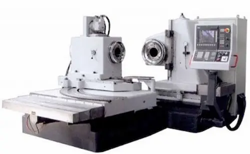
RTM800-C2 univerzális kúpkerék gördítőpróbagép: Ez a csúcstechnológia szükséges a kúpfogaskerekek minőségi és csendes működéséhez. Pontosan elemzi a fogazat érintkezést, DIN 5-ös pontossággal. Akár 800 mm átmérőjű kerekeket is képes tesztelni. Fő komponensei: robusztus acélváz, nagy pontosságú mérőrendszer, felhasználóbarát érintőképernyős vezérlőpult. Kiválóan alkalmazható autóipari, repülőgép-ipari és nehézgéppari fogaskerék-gyártásban. Fő előnyei: kivételes megbízhatóság, gyors tesztciklus-idő, könnyű üzemeltetés. A precíz gördülésvizsgálat kulcsa a hibátlan fogazathoz, csökkenti a zajszintet és növeli a termék élettartamát. A tartós kivitel és a magas ismételhetőség biztosítja a hosszú távú befektetés megtérülését.
RTM800-C2 Καθολική Μηχανή Δοκιμής Έκκεντρης Κίνησης Τροχών: Απαραίτητη για τον έλεγχο ποιότητας και την ήσυχη λειτουργία κωνικών γραναζιών. Αναλύει με ακρίβεια την επαφή των δοντιών, επιτυγχάνοντας ακρίβεια DIN 5. Δοκιμάζει γρανάζια έως 800 mm. Βασικά στοιχεία: ανθεκτικό χάλυβα πλαίσιο, υψηλής ακρίβειας σύστημα μέτρησης, φιλικό προς τον χρήστη πλαίσιο ελέγχου οθόνης αφής. Ιδανικό για την παραγωγή αυτοκινήτων, αεροσκαφών και βαρέως μηχανικού εξοπλισμού. Βασικά πλεονεκτήματα: αξιοπιστία, γρήγορος χρόνος κύκλου δοκιμής, εύκολη λειτουργία. Ο ακριβής έλεγχος κύλισης είναι κρίσιμος για την άψογη εμπλοκή, μειώνει το θόρυβο και αυξάνει τη διάρκεια ζωής του προϊόντος. Η ανθεκτική κατασκευή και η υψηλή επαναληψιμότητα εξασφαλίζουν μακροπρόθεσμη απόδοση.
RTM800-C2 Univerzální stroj pro valivou zkoušku kuželových kol: Nezbytný pro kontrolu kvality a tichý chod kuželových ozubených kol. Přesně analyzuje záběr zubů s přesností DIN 5. Testuje kola o průměru až 800 mm. Klíčové komponenty: robustní ocelový rám, vysoce přesný měřicí systém, uživatelsky přívětivé ovládání s dotykovým panelem. Ideální pro výrobu ozubených kol v automobilovém, leteckém a těžkém průmyslu. Hlavní výhody: výjimečná spolehlivost, rychlý cyklus testování, snadná obsluha. Přesný valivý test je klíčem k bezchybnému záběru, snižuje hlučnost a prodlužuje životnost výrobku. Odolná konstrukce a vysoká opakovatelnost zajišťují dlouhodobou návratnost investice.
RTM800-C2 Универсална машина за валцово изпитване на конични зъбни колела: Необходима за контрол на качеството и тихата работа на конични зъбни колела. Точен анализ на зъбното зацепване с точност DIN 5. Тества колела с диаметър до 800 mm. Основни компоненти: здрава стоманена рамка, високо точно измервателно устройство, лесен за употреба сензорен контролен панел. Приложима в автомобилната, авиационната и тежката индустрия. Ключови предимства: изключителна надеждност, бърз тестов цикъл, лесна експлоатация. Прецизният валцов тест е ключов за безупречното зацепване, намалява шума и удължава експлоатационния живот. Здравата конструкция и високата повторяемост гарантират дългосрочна възвръщаемост.
RTM800-C2 Универзална машина за ролно испитивање коничних зупчаника: Неопходна за контролу квалитета и тих рад коничних зупчаника. Прецизно анализира заузимање зуба са тачношћу DIN 5. Испитује зупчанике пречника до 800 мм. Главни делови: робустни челични оквир, високо прецизан мерни систем, једноставан сензорни панел за управљање. Идеална за производњу у аутомобилској, авио и тешкој индустрији. Предности: изузетна поузданост, брз циклус тестирања, лака употреба. Прецизно ролно испитивање је кључно за безупречно заузимање, смањује буку и продужава век трајања. Робусна конструкција и висока поновљивост обезбеђују дугорочну исплативост улагања.
RTM800-C2 Univerzálny stroj na valivé skúšanie kužeľových ozubených kolies: Nevyhnutný pre kontrolu kvality a tichý chod kužeľových ozubených kolies. Presne analyzuje záber zubov s presnosťou DIN 5. Testuje kolesá s priemerom do 800 mm. Kľúčové komponenty: robustná oceľová konštrukcia, vysoko presný merací systém, užívateľsky prívetivé ovládanie s dotykovým panelom. Ideálne pre výrobu ozubených kolies v automobilovom, leteckom a ťažkom priemysle. Hlavné výhody: výnimočná spoľahlivosť, rýchly skúšobný cyklus, jednoduchá obsluha. Presný valivý test je kľúčový pre bezchybný záber, znižuje hlučnosť a predlžuje životnosť výrobku. Odolná konštrukcia a vysoká opakovateľnosť zabezpečujú dlhodobú návratnosť investície.
RTM800-C2 Univerzalni stroj za valjno ispitivanje konusnih zupčanika: Neophodan za kontrolu kvalitete i tihi rad konusnih zupčanika. Precizno analizira zahvat zuba s točnošću DIN 5. Testira zupčanike promjera do 800 mm. Ključne komponente: robusni čelični okvir, visokoprecizni mjerni sustav, jednostavno upravljanje putem dodirnog zaslona. Idealno za proizvodnju u automobilskoj, zrakoplovnoj i teškoj industriji. Prednosti: iznimna pouzdanost, brz ciklus testiranja, lako korištenje. Precizno valjno ispitivanje ključno je za besprijekoran zahvat, smanjuje buku i produžuje vijek trajanja. Čvrsta konstrukcija i visoka ponovljivost osiguravaju dugoročan povrat ulaganja.
RTM800-C2 Univerzalni stroj za valjno preizkušanje stožčastih zobnikov: Nujen za nadzor kakovosti in tihi obratovanje stožčastih zobnikov. Natančno analizira zobni prijem z natančnostjo DIN 5. Preizkuša zobnike premera do 800 mm. Glavne komponente: robusten jeklen okvir, visoko natančen merilni sistem, enostaven uporabniški vmesnik s tipkovnico. Uporaben v avtomobilski, letalski in težki industriji. Glavne prednosti: izjemna zanesljivost, hiter cikel testiranja, enostavna uporaba. Natančno valjno preizkušanje je ključnega pomena za brezhiben prijem, zmanjšuje hrup in podaljšuje življenjsko dobo. Trpežna konstrukcija in visoka ponovljivost zagotavljata dolgoročno donosnost naložbe.
RTM800-C2 Універсальний машина для роликового тестування конічних зубчастих коліс: Необхідна для контролю якості та безшумної роботи конічних зубчастих коліс. Точний аналіз зачеплення зубів з точністю DIN 5. Тестує колеса діаметром до 800 мм. Основні компоненти: міцна сталева рама, високоточна вимірювальна система, зручний сенсорний пульт керування. Ідеальна для виробництва у автомобільній, авіаційній та важкій промисловості. Переваги: виняткова надійність, швидкий цикл тестування, проста експлуатація. Точне роликове тестування є ключовим для бездоганного зачеплення, знижує шум та збільшує термін служби. Міцна конструкція та висока повторюваність забезпечують довгострокову окупність інвестицій.