| Model | Unit | BG800 | |
| Type | D3 | ||
| CNC system | SIEMENS 828D | ||
| Work to be machined | Max. module | mm | 15 |
| Max. pitch cone distance (spiral angle 0°/15°/30°) | mm | 285/350/420 | |
| Pitch angle of workpiece | 5-90° | ||
| Max gear ratio (shaft angle 90°) | 10:1 | ||
| Max. pitch diameter at ratio 10:1 (spiral angle 0°/15°/30°) | mm | 575/700/800 | |
| Max. pitch diameter at ratio 2:1 (spiral angle 0°/15°/30°) | mm | 520/635/750 | |
| Max. pitch diameter at ratio 1:1 (spiral angle 0°/15°/30°) | mm | 395/500/600 | |
| Max. face width | mm | 100 | |
| Spiral angle | 0-45° | ||
| Max. cutting depth | mm | 32 | |
| NO. of teeth | 4-100 | ||
| Cutter diameter | 6″, 9″, 12″, 18″ | ||
| Work spindle | Distance from face of spindle to machine center | mm | 125-600 |
| Reading of each graduation for scale/vernier showing the distance | mm | 1/0.02 | |
| Downward from center position when the distance from face of spindle to machine center is: 125-270/270-330/330-540 | mm | 25/70/90 | |
| Upward from center position | mm | 90 | |
| Reading of each graduation for scale/vernier showing the upward and downward | mm | 1/0.02 | |
| Diameter of taper hole at large end | mm | Φ153 | |
| Taper | 1:20 | ||
| Taper length | mm | 180 | |
| Diameter of through hole | mm | Φ125 | |
| Diameter of flange | mm | Φ235 | |
| Cradle set up | Setting angle | 0-360° | |
| Reading of each graduation for scale/vernier showing the setting angle | 1’/180° | ||
| Eccentric setting angle | 0-340° | ||
| Radial setting of cutter | 0-20’ | ||
| Reading of each graduation for scale/vernier showing the eccentric setting angle | 1’/60° | ||
| Max cradle roll angle | 60° | ||
| Sliding base | Max. movement from center | mm | Forward 25, Backward 150 |
| Other | Main motor power | kW | 15 |
| Total capacity | kVA | 35 | |
| Overall dimension | mm | 2900x2750x2200 | |
| Net weight | kg | 12500 | |
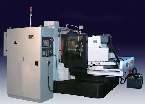
A BG800-D3 é uma máquina geradora de engrenagens cônicas espirais de última geração, essencial para fabricação de engrenagens cônicas espirais de alta precisão (engrenagem coroa e pinhão espiral). Utilizando o método de geração contínua (Face Milling ou Face Hobbing), produz engrenagens silenciosas e de alto desempenho para eixos não paralelos. Com capacidade para diâmetros máximos de peça de 800 mm e módulo 16, atinge a exigente qualidade de dentes DIN 5. Sua construção robusta com base rígida, cabeçote de corte potente e eixos de alta rigidez garante produtividade excepcional em séries médias a grandes. Configurações opcionais incluem automação para carregamento/descarregamento. Aplicações-chave: eixos traseiros de veículos pesados (caminhões, ônibus), equipamentos agrícolas, mineração, energia eólica e transmissões industriais. Vantagens: Alta eficiência de corte, repetibilidade exata, manutenção reduzida e vida útil prolongada. Componentes principais: Estrutura fundida, mesa rotativa CNC, cabeçote gerador, sistema de avanço CNC, painel de controle FANUC. Máquina confiável para fabricantes globais de engrenagens exigentes.
Ang BG800-D3 ay isang pangunahing spiral bevel gear generating machine (makina sa paggawa ng spiral bevel gear) na ginagamit para sa mataas na presisyon na spiral bevel gear cutting (pagputol ng gear). Gumagamit ito ng continuous generating method (Face Milling o Face Hobbing) upang makagawa ng tahimik at malakas na spiral bevel gears para sa mga aplikasyon na may intersecting shafts. Kakayahan nito: hanggang 800mm na maximum workpiece diameter, module 16, at nakakamit ng DIN class 5 gear quality. Matibay ang disenyo nito na may matatag na base, malakas na cutting head, at high rigidity CNC axes para sa mataas na productivity sa medium hanggang high volume production. May mga CNC machine options para sa automation. Pangunahing gamit sa: heavy-duty truck at bus rear axles, agricultural machinery, mining equipment, wind power gearboxes, industrial gearbox manufacturing. Mga pakinabang: Napakataas na cutting efficiency, superb accuracy, mahusay na reliability, mababang maintenance cost. Pangunahing bahagi: Cast iron frame, CNC rotary table, generating head unit, CNC feed system, FANUC control panel. Angkop para sa mga gear manufacturer na nangangailangan ng matibay at tumpak na spiral bevel gear cutting machine para sa mga drive axle at iba pang heavy-duty na gamit.
La BG800-D3 è una macchina generatrice per ruote coniche a denti elicoidali (macchina per dentare coniche spirali) di precisione industriale. Utilizza il metodo di generazione continua (Face Milling o Face Hobbing) per produrre ruote coniche a spirale silenziose e resistenti per assi non paralleli. Specifiche chiave: diametro massimo pezzo 800 mm, modulo 16, qualità del dentatura DIN 5. La struttura robusta in ghisa, la potente testa di taglio e gli assi CNC ad alta rigidità garantiscono elevata produttività per medie e grandi serie. Opzioni includono automazione per carico/scarico. Campi di applicazione primari: assali posteriori per autocarri e autobus pesanti, macchine agricole, settore minerario, energia eolica, trasmissioni industriali. Vantaggi: Efficienza di taglio eccezionale, precisione e ripetibilità costanti, affidabilità operativa e bassa manutenzione. Componenti principali: Base in ghisa, tavola rotante CNC, unità generatrice, sistema di avanzamento CNC, controllo FANUC. Soluzione affidabile per la produzione di ingranaggi conici di alta qualità per settori demanding.
BG800-D3, yüksek hassasiyetli spiral konik dişli (spiral bevel dişli) üretimi için endüstriyel sınıf bir spiral konik dişli üretim makinesidir. Sürekli üretim yöntemi (Face Milling veya Face Hobbing) kullanarak kesişen miller için sessiz ve güçlü spiral konik dişliler üretir. Kapasitesi: maksimum 800mm iş parçası çapı, modül 16, DIN 5 sınıfı dişli kalitesi. Sağlam döküm gövdesi, güçlü kesici kafası ve yüksek rijitlikli CNC eksenleri ile orta ve yüksek seri üretimde yüksek verimlilik sunar. CNC tezgahı opsiyonları arasında otomasyon bulunur. Başlıca uygulamalar: ağır hizmet kamyon ve otobüs arka aksları, tarım makineleri, madencilik ekipmanları, rüzgar enerjisi dişli kutuları, endüstriyel dişli kutusu üretimi. Avantajları: Üstün kesim verimliliği, mükemmel hassasiyet ve tekrarlanabilirlik, yüksek güvenilirlik, düşük bakım maliyeti. Ana bileşenler: Döküm şasi, CNC döner tabla, üretim ünitesi (generating head), CNC ilerleme sistemi, FANUC kontrol paneli. Ağır hizmet sürüş aksları ve diğer zorlu uygulamalar için kaliteli spiral konik dişli üretmek isteyen dişli üreticilerinin tercihi.
La BG800-D3 est une machine à tailler les engrenages coniques à denture spirale (machine à tailler les engrenages coniques spirales) de haute précision pour la production industrielle. Elle emploie la méthode de taillage par génération continue (Face Milling ou Face Hobbing) pour usiner des engrenages coniques spirales silencieux et robustes pour axes concourants. Caractéristiques majeures : diamètre max. pièce 800 mm, module 16, qualité de denture DIN 5. Sa construction robuste en fonte, sa puissante tête de coupe et ses axes CNC à grande rigidité assurent une productivité élevée en moyennes et grandes séries. Options incluant l'automatisation de chargement/déchargement. Applications principales : essieux arrière pour poids lourds et bus, machines agricoles, équipement minier, éoliennes, transmissions industrielles. Avantages : Efficacité d'usinage exceptionnelle, précision et répétabilité constantes, fiabilité opérationnelle et maintenance réduite. Composants clés : Banc en fonte, table tournante CNC, unité génératrice, système d'avance CNC, commande FANUC. Solution fiable pour la fabrication d'engrenages coniques de qualité supérieure pour secteurs exigeants.
آلة BG800-D3 هي ماكينة توليف تروس مخروطية حلزونية (ماكينة تشكيل التروس المخروطية الحلزونية) عالية الدقة للتصنيع الصناعي. تستخدم طريقة التوليف المستمر (الطحن الوجهي أو القطع الوجهي) لإنتاج تروس مخروطية حلزونية هادئة وقوية للمحاور المتقاطعة. المواصفات الرئيسية: قطر الشغل الأقصى 800 مم، الموديول 16، جودة التروس وفق DIN 5. هيكلها الصلب من الحديد الزهر، رأس القطع القوي، ومحاور CNC عالية الصلابة تضمن إنتاجية عالية للإنتاج متوسط وكبير الحجم. تتضمن الخيارات التشغيل الآلي للتحميل/التفريغ. التطبيقات الأساسية: محاور خلفية للشاحنات والحافلات الثقيلة، المعدات الزراعية، التعدين، صناديق تروس طاقة الرياح، صناعة صناديق التروس الصناعية. المزايا: كفاءة قطع استثنائية، دقة وثبات فائقين، موثوقية تشغيلية عالية، وصيانة منخفضة التكلفة. المكونات الرئيسية: هيكل من الحديد الزهر، طاولة دوارة CNC، وحدة توليف، نظام تغذية CNC، لوحة تحكم FANUC. حل موثوق لتصنيع تروس مخروطية عالية الجودة لقطاعات متطلبة.
Die BG800-D3 ist eine Hochpräzisions-Spiralkegelrad-Erzeugungsmaschine (Spiralkegelradfräsmaschine) für die industrielle Fertigung. Sie nutzt das kontinuierliche Erzeugungsverfahren (Face Milling oder Face Hobbing) zur Herstellung leiser und leistungsstarker Spiralkegelräder für sich schneidende Achsen. Kernparameter: Maximaler Werkstückdurchmesser 800 mm, Modul 16, Verzahnungsqualität DIN 5. Die robuste Gusseisenkonstruktion, der leistungsstarke Schneidkopf und hochsteife CNC-Achsen garantieren hohe Produktivität in mittleren und großen Serien. Automatisierungsoptionen für Be- und Entladung verfügbar. Hauptanwendungen: Hinterachsen für LKW und Busse, Landmaschinen, Bergbauausrüstung, Windkraftgetriebe, Industriegetriebefertigung. Vorteile: Herausragende Zerspanungseffizienz, exzellente Genauigkeit und Wiederholgenauigkeit, hohe Betriebszuverlässigkeit, geringer Wartungsaufwand. Hauptkomponenten: Gussbett, CNC-Rundtisch, Erzeugungskopf (Generating Head), CNC-Vorschubsystem, FANUC-Steuerung. Zuverlässige Lösung für die Herstellung hochwertiger Spiralkegelräder für anspruchsvolle Einsatzbereiche wie Antriebsachsen.
De BG800-D3 is een hoogwaardige spiraalconische tandwielgenererende machine (spiraalkegelwielfreesmachine) voor industriële productie. Hij gebruikt de continue generatiemethode (Face Milling of Face Hobbing) om stille en sterke spiraalconische tandwielen te maken voor kruisende assen. Belangrijke specificaties: maximaal werkstukdiameter 800 mm, module 16, tandkwaliteit DIN 5. Robuust gietijzeren frame, krachtige snijkop en stijve CNC-assen zorgen voor hoge productiviteit in middelgrote tot grote series. Automatiseringsopties voor laden/lossen beschikbaar. Belangrijkste toepassingen: achterassen voor zware trucks en bussen, landbouwmachines, mijnbouwmaterieel, windturbine-vertragingskasten, industriële versnellingsbakproductie. Voordelen: Uitstekende snij-efficiëntie, superieure nauwkeurigheid en herhaalbaarheid, hoge bedrijfsbetrouwbaarheid, lage onderhoudskosten. Hoofdcomponenten: Gietijzeren frame, CNC-draaitafel, genererende kop (generating head), CNC-voedsysteem, FANUC-besturingspaneel. Betrouwbare oplossing voor het maken van hoogwaardige spiraalconische tandwielen voor veeleisende toepassingen zoals aandrijfassen.
Maszyna BG800-D3 to zaawansowana obrabiarka do obróbki kół zębatych stożkowych śrubowych (frezarka do kół stożkowych śrubowych) o wysokiej precyzji dla przemysłu. Wykorzystuje metodę obróbki obwiedniowej ciągłej (Face Milling lub Face Hobbing) do wytwarzania cichych i wytrzymałych kół stożkowych śrubowych dla przecinających się osi. Kluczowe parametry: maks. średnica obrabiania 800 mm, moduł 16, klasa dokładności zębów DIN 5. Solidna konstrukcja z żeliwa, wydajna głowica skrawająca i sztywne osie CNC gwarantują wysoką produktywność w średnich i dużych seriach. Dostępne opcje automatyzacji załadunku/rozładunku. Główne zastosowania: mosty napędowe ciężarówek i autobusów, maszyny rolnicze, sprzęt górniczy, skrzynie przekładniowe w energetyce wiatrowej, produkcja przemysłowych przekładni. Zalety: Wyjątkowa wydajność skrawania, doskonała dokładność i powtarzalność, wysoka niezawodność eksploatacyjna, niskie koszty utrzymania. Główne komponenty: Łoże odlewane, stół obrotowy CNC, głowica obwiedniowa (generating head), system posuwu CNC, panel sterujący FANUC. Niezawodne rozwiązanie do produkcji wysokiej jakości kół stożkowych śrubowych do wymagających zastosowań, takich jak osie napędowe.
Mașina BG800-D3 este o mașină de generat unelte conice spiralate (mașină de frezat unelte conice spiralate) de precizie industrială. Utilizează metoda de generare continuă (Freza frontală sau Danturare frontală) pentru a prelucra unelte conice spiralate silențioase și durabile pentru arbori concurenți. Specificații cheie: diametru maxim piesă 800 mm, modul 16, calitate dinți DIN 5. Construcția robustă din fontă, capul de așchiere puternic și axele CNC rigide asigură productivitate ridicată în serii medii și mari. Opțiuni includ automatizare încărcare/descărcare. Aplicații principale: punți spate pentru camioane și autobuze grele, utilaje agricole, echipamente miniere, cutii de viteze eoliene, producție de cutii de viteze industriale. Avantaje: Eficiență de așchiere excepțională, precizie și repetabilitate superioară, fiabilitate operațională ridicată, costuri de întreținere reduse. Componente principale: Bază din fontă, masă rotativă CNC, cap de generare (generating head), sistem de avans CNC, panou de control FANUC. Soluție fiabilă pentru fabricarea uneltelor conice spiralate de înaltă calitate pentru aplicații solicitante precum arbori de antrenare.
A BG800-D3 spirális fogaskerekek generálására tervezett, nagy teljesítményű gépgár. Ez az öttengelyes CNC megmunkáló központ kiemelkedő pontosságot (IT5 szint) és megbízhatóságot kínál Φ800 mm-es munkadarab-átmérőig, kiválóan alkalmas keményfém megmunkálásra. Siemens 840D sl rendszerrel, precíz forgácsolási folyamatokat biztosít spirálkúpfogaskerekek, hipoid fogaskerekek, egyenes kúpfogaskerekek és csigakerékpárok gyártásához. Fő alkalmazási területei közé tartozik a nehézgépjármű-ipar, mezőgazdasági gépek, robotika és energiaipari berendezések. Fő előnyei: kiemelkedő merevség, nagy stabilitás, alacsony zajszint, hosszú szerszámélettartam és kiváló felületi minőség. Fő komponensek: magas szilárdságú öntöttváz, precíziós orsók, digitális hajtások, automatizált szerszámcsere és fejlett hűtőrendszer. Felhasználók kiemelten értékelik a kiváló ár-érték arányt, az alacsony karbantartási igényt és a kiterjedt globális szervizhálózatot, ami minimális állásidőt garantál.
Το BG800-D3 είναι μια κορυφαίας τεχνολογίας μηχανή 5 αξόνων με CNC για την κατασκευή σπειροειδών κωνικών γραναζιών. Αποτελεί λύση υψηλής ακριβείας (έως IT5) και παραγωγικότητας για επεξεργασία σκληρών υλικών, με μέγιστη διάμετρο τεμαχίου Φ800 mm. Εξοπλισμένο με σύστημα Siemens 840D sl, διασφαλίζει άψογο τελικό αποτέλεσμα για σπειροειδή κωνικά γραναζιά, υποειδή γρανάζια, ευθύγραμμα κωνικά γρανάζια και οδοντωτούς τροχούς σκώρου. Ευρέως χρησιμοποιείται σε βαρύ εξοπλισμό, γεωργικά μηχανήματα, ρομποτική και βιομηχανίες ενέργειας. Βασικά πλεονεκτήματα: άκαμπτη κατασκευή, εξαιρετική σταθερότητα, χαμηλός θόρυβος λειτουργίας, μεγάλη διάρκειας εργαλείων και άριστη ποιότητα επιφάνειας. Βασικές ενότητες: ανθεκτικό χυτοσίδηρο πλαίσιο, υψηλής ακρίβειας άξονες, ψηφιακές κινήσεις, αυτόματη αλλαγή εργαλείων (ATC) και προηγμένο σύστημα ψύξης. Οι χρήστες εκτιμούν την αξιόπιστη λειτουργία, το χαμηλό κόστος κατεργασίας ανά τεμάχιο και την ευκολία συντήρησης, εξασφαλίζοντας συνεχή παραγωγικότητα.
BG800-D3 je špičkový 5osý CNC obráběcí stroj speciálně navržený pro výrobu kuželových ozubených kol se šroubovicovými zuby. Tento vysoce přesný stroj (až IT5) zvládá obrábění tvrdých materiálů s maximálním průměrem obrobku Φ800 mm. Díky řídicímu systému Siemens 840D sl zajišťuje vynikající kvalitu pro spirálová kuželová kola, hypoidní kola, rovná kuželová kola a čelní soukolí. Hlavní nasazení: těžká technika, zemědělské stroje, robotika a energetika. Klíčové výhody: robustní konstrukce, výjimečná stabilita, nízká hlučnost, dlouhá životnost nástrojů a výborná jakost povrchu. Základní komponenty: vysoce tuhý litinový rám, přesná vřetena, digitální pohony, automatická výměna nástrojů a pokročilý chladicí systém. Uživatelé oceňují jeho spolehlivost, nízké provozní náklady, snadnou obsluhu a minimální nároky na údržbu, což z něj činí ideální volbu pro náročné aplikace s požadavkem na maximální výtěžnost.
BG800-D3 е високопроизводителна 5-осова CNC машина за производство на спирални конични зъбни колела. Този прецизен (до IT5) и надежден стан обработва твърди материали с диаметър на детайла до Φ800 mm. Оборудван със система Siemens 840D sl, той гарантира безупречно качество при изработка на спирални конични зъбни колела, хипоидни зъбни колела, прави конични зъбни колела и червячни предавки. Приложения: тежко машиностроене, селскостопанска техника, роботика и енергетика. Основни предимства: висока твърдост, изключителна стабилност, ниски нива на шум, дълъг живот на инструмента и отлично качество на повърхността. Основни компоненти: здрава чугунена конструкция, прецизни шпиндели, дигитални задвижвания, автоматична смяна на инструменти (ATC) и напреднала система за охлаждане. Потребителите ценят високата му производителност, лекотата на поддръжка и ниските експлоатационни разходи, осигуряващи бърза възвращаемост на инвестицията.
BG800-D3 је високопрецизна 5-осна CNC машина за генерисање спиралних коничних зупчаника. Овај поуздани и робусни стан обрађује тврде материјале са пречником дела до Φ800 mm и постиже изузетну тачност (до IT5). Опремљен системом Siemens 840D sl, обезбеђује врхунски квалитет за спирална конична зупчаника, хипоидна зупчаника, права конична зупчаника и зупчасте предавке са змијским зупчаницима. Примарне примене: тешка опрема, пољопривредне машине, роботика и енергетска индустрија. Кључне предности: крута конструкција, изванредна стабилност, тиха рад, дуги век трајања алата и одлична квалитет површине. Главни компоненти: чврсто ливено оквир, прецизни вретена, дигитални погони, аутоматска смена алата (ATC) и напредни систем за хлађење. Корисници истичу његову ефикасност, високу продуктивност, минимално време нерада и једноставно одржавање, што га чини идеалним за серијску производњу у погонским преносима.
BG800-D3 je vysoko výkonný 5-osý CNC stroj na výrobu špirálových kužeľových ozubených kolies. Tento presný (až IT5) a spoľahlivý stroj spracováva tvrdé materiály s maximálnym priemerom obrobku Φ800 mm. Vybavený systémom Siemens 840D sl zabezpečuje vynikajúcu kvalitu pre špirálové kužeľové kolesá, hypoidné kolesá, rovné kužeľové kolesá a čelové prevody. Hlavné oblasti použitia: ťažké strojárstvo, poľnohospodárske stroje, robotika a energetika. Kľúčové výhody: tuhá konštrukcia, vynikajúca stabilita, nízka hlučnosť, dlhá životnosť nástrojov a vynikajúca kvalita povrchu. Hlavné komponenty: vysokopevnostné liatinové telo, presné vretená, digitálne pohony, automatická výmena nástrojov (ATC) a pokročilý chladiaci systém. Používatelia oceňujú jeho jednoduchú obsluhu, nízke náklady na údržbu a vysokú produktivitu, čo zaisťuje rýchlu návratnosť investície.
BG800-D3 je vrhunski 5-osni CNC stroj za izradu spiralnih konusnih zupčanika. Ovaj precizni (do IT5) i izuzetno pouzdan stroj obrađuje tvrde materijale s promjerom izratka do Φ800 mm. Opremljen Siemens 840D sl upravljačkim sustavom, jamči vrhunsku kvalitetu za spiralne konične zupčanike, hipoidne zupčanike, ravne konične zupčanike i pužne prijenosnike. Primjena u: teškom strojarstvu, poljoprivrednim strojevima, roboticima i energetici. Glavne prednosti: kruta konstrukcija, izvrsna stabilnost, tihi rad, dugi vijek trajanja alata i izvrsna kvaliteta površine. Ključne komponente: visokokrutna lijevana konstrukcija, precizna vretena, digitalni pogoni, automatska izmjena alata (ATC) i napredni sustav hlađenja. Korisnici ističu njegovu visoku učinkovitost, minimalno vrijeme zastoja i lako održavanje, čineći ga idealnim za serijsku proizvodnju u zahtjevnim uvjetima.
BG800-D3 je vrhunski 5-osni CNC stroj za izdelavo spiralnih stožčastih zobnikov. Ta natančen (do IT5) in zanesljiv stroj obdeluje trde materiale s premerom obdelovanca do Φ800 mm. Opremljen s krmilnikom Siemens 840D sl zagotavlja vrhunsko kakovost za spiralne stožčaste zobnike, hipoidne zobnike, ravne stožčaste zobnike in čelne zobniške prenose. Glavne aplikacije: težka industrija, kmetijski stroji, robotika in energetika. Ključne prednosti: toga konstrukcija, izjemna stabilnost, tih delovanje, dolga življenjska doba orodja in odlična kakovost površine. Glavne komponente: visoko togo lito ogrodje, natančni vretenci, digitalni pogoni, samodejno menjalnik orodja (ATC) in napreden hladilni sistem. Uporabniki cenijo njegovo visoko produktivnost, enostavno vzdrževanje in minimalne izpadne čase, kar zagotavlja optimalno izkoriščenost stroja v avtomobilski industriji in drugih zahtevnih okoljih.
BG800-D3 — високопродуктивний 5-координатний верстат з ЧПУ для нарізання спіральних конічних зубчастих коліс. Цей точний (до IT5) та надійний верстат обробляє тверді матеріали з діаметром заготовки до Φ800 мм. Обладнаний системою керування Siemens 840D sl, він забезпечує високу якість виробів: спіральні конічні колеса, гіпоїдні колеса, прямі конічні колеса та черв'ячні передачі. Основні сфери застосування: важке машинобудування, сільгосптехніка, робототехніка та енергетика. Ключові переваги: жорстка конструкція, висока стабільність, низький рівень шуму, довгий термін служби інструменту та відмінна якість поверхні. Основні вузли: міцна чавунна станина, прецизійні шпинделі, цифрові приводи, автоматична зміна інструменту (АЗІ) та передова система охолодження. Користувачі відзначають його високу ефективність, зручне обслуговування та мінімальний час простою, що робить його ідеальним вибором для серійного виробництва трансмісій для вантажівок, тракторного обладнання та інших відповідальних вузлів.