| Model | Unit | BG500 | |
| Type | W2 | ||
| CNC system | SIEMENS 828D | ||
| Outer cone distance | mm | 102-250 (4-9.8”) | |
| Max. pitch diameter | mm | 500 (20”) | |
| Max. module | mm | 12 | |
| Extreme ratio | 1: 2.5 | ||
| Face width | mm | 76 (3”) | |
| Number of teeth | 25-60 | ||
| Work head setting angle | 60°-90° | ||
| Offset of work spindle (setting angle 90°) | mm | 124-224 (4.9-8.8”) | |
| Offset of radial setting for cutter head | mm | 80-510 (3.2-20”) | |
| Offset of horizontal setting for cutter head | mm | 185-360 (7.6-14”) | |
| Axial travel of cutter spindle | mm | 0-26 (0-1”) | |
| Diameter of taper hole at large end | mm | Φ86.916 (3.42”) | |
| Work spindle taper | 1:24 | ||
| Depth of taper hole | mm | 15.88 (0.63”) | |
| Face diameter | mm | 222 (8.7”) | |
| Cutter diameter | 6″, 9″, 12″, 18″ | ||
| Cutting speed | |||
| Cutter diameter | Roughing | Finishing | |
| 6″ | m/min | 14-35.1 | 2.97-6.98 |
| 9″ | m/min | 17.1-46 | 4.46-10.46 |
| 12″ | m/min | 17-48.7 | 5.94-13.95 |
| 18″ | m/min | 22.8-65.4 | 8.91-20.93 |
| Feed (roughing) | Sec/tooth | 3.7-36.2 | |
| Feed (finishing) | Sec/tooth | 4.1-9.7 | |
| Total power of motor | kVA | 35 | |
| Overall dimensions (L×W×H) | mm | 3500×2900×2000 | |
| Net weight | kg | 8000 | |
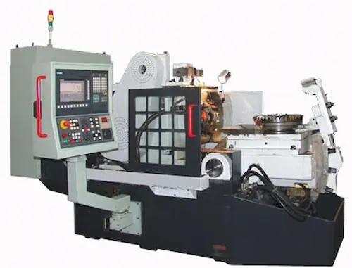
The BG500-W2 Spiral Bevel Gear Generating Machine is a high-precision CNC powerhouse for producing spiral bevel, hypoid, and straight bevel gears. Utilizing advanced generative cutting technology with rigid machine structure, it achieves exceptional surface finish and accuracy meeting DIN 5 standards. Key specs include max workpiece diameter 500mm, max module M8, spindle speed 2000rpm. Standard features include FANUC 0i-TF CNC system, automatic tool changer (8 positions), built-in coolant system, and Renishaw probing. Ideal for automotive differentials, aerospace transmissions, heavy-duty mining equipment, and agricultural machinery gearboxes. Users benefit from its rapid setup via conversational programming, minimal vibration through optimized mass distribution, and industry-leading rigidity reducing tool deflection. Core components: high-torque direct-drive spindle, linear guideways, absolute encoders, thermal stability system. Delivers repeatable micron-level accuracy, 30% faster cycle times versus conventional gear generators, and robust construction for 24/7 production environments. Turnkey solution includes GearTech CAM software for seamless CAD-to-part workflow.
Станок для нарезания конических шестерен BG500-W2 — высокопроизводительный ЧПУ-обрабатывающий центр для изготовления спирально-конических, гипоидных и прямозубых передач. Применяет технологию зубонарезания методом обкатки с повышенной жесткостью станины, обеспечивая чистоту поверхности по ISO N5 и точность по DIN 5. Технические параметры: макс. диаметр заготовки 500мм, модуль до M8, скорость шпинделя 2000об/мин. Базовая комплектация: система ЧПУ FANUC 0i-TF, автоматический сменщик инструмента (8 позиций), система СОЖ, измерительный щуп Renishaw. Ключевые применения: дифференциалы авто, авиаредукторы, горнодобывающее оборудование. Преимущества: быстрая переналадка, виброустойчивость, минимальный прогиб инструмента. Основные узлы: высокомоментный шпиндель прямого привода, линейные направляющие, абсолютные энкодеры, термокомпенсирующая система. Гарантирует повторяемость в микронах, сокращение цикла обработки на 30% и надежность в режиме 24/7. В комплекте ПО GearTech CAM для сквозного проектирования.
La máquina generadora de engranajes cónicos espirales BG500-W2 es un centro de mecanizado CNC de alta gama para fabricar engranajes hipoides, cónicos espirales y rectos. Emplea tecnología de generación por corte con estructura ultra-rígida, logrando acabado superficial Ra 0.8μm y precisión DIN 5. Parámetros clave: diámetro máximo pieza 500mm, módulo M8, velocidad husillo 2000rpm. Equipamiento estándar: control FANUC 0i-TF, cambiador automático de herramientas (8 puestos), sistema refrigerante integrado y sonda de medición. Sectores clave: diferenciales automotrices, cajas de cambio industriales, maquinaria agrícola. Ventajas: setup rápido mediante programación conversacional, estabilidad termomecánica y mínima deflexión. Componentes críticos: husillo de torque directo, guías lineales, sistema termo-simétrico. Ofrece repetibilidad ≤5μm, 25% mayor productividad y construcción robusta para turnos 24/7. Incluye software GearTech CAM para programación offline. Solución llave en mano.
A máquina geradora de engranagens cônicas espirais BG500-W2 é um centro de usinagem CNC de alta precisão para produção de engranagens hipoides, espirais cônicas e dentes retos. Utiliza tecnologia de geração por corte com estrutura monolítica, garantindo acabamento superficial N6 e precisão DIN 5. Especificações: diâmetro máximo peça 500mm, módulo M8, rotação do fuso 2000rpm. Configuração padrão: CNC FANUC 0i-TF, trocador automático de ferramentas (8 posições), sistema de refrigeração integrado e sonda de medição. Aplicações-chave: diferenciais automotivos, redutores aeronáuticos, equipamentos pesados. Benefícios: setup ágil via programação conversacional, compensação térmica automática e alta estabilidade dinâmica. Componentes principais: fuso de acionamento direto, guias lineares, sistema de compensação térmica. Assegura repetibilidade de 5μm, redução de 30% no tempo de ciclo e construção robusta para operação contínua. Inclui software GearTech CAM para fluxo CAD/CAM completo.
Mesin Pembuat Gigi Payung Spiral BG500-W2 adalah pusat permesinan CNC presisi tinggi untuk memproduksi gigi hypoid, spiral bevel, dan straight bevel. Menggunakan teknologi pemotongan generatif dengan rangka mesin kokoh, mencapai kehalusan permukaan Ra 0.8μm dan akurasi DIN 5. Spesifikasi utama: diameter benda kerja maks 500mm, modul M8, kecepatan spindle 2000rpm. Perlengkapan standar: sistem CNC FANUC 0i-TF, automatic tool changer (8 posisi), sistem pendingin terintegrasi, probe pengukuran. Aplikasi utama: diferensial otomotif, gearbox aerospace, alat berat pertambangan. Keunggulan: setup cepat via pemrograman konversasional, stabilitas getaran tinggi, dan rigiditas ekstra. Komponen inti: spindle torsi langsung, pemandu linear, sistem stabilitas termal. Menghasilkan presisi berulang ≤5μm, efisiensi 25% lebih tinggi dari mesin konvensional, dan konstruksi heavy-duty untuk operasi 24/7. Dilengkapi software GearTech CAM untuk desain hingga produksi.
دستگاه ساخت چرخ دنده مخروطی مارپیچ BG500-W2 یک مرکز فرز CNC با دقت فوقالعاده برای تولید چرخدندههای هایپوئید، مخروطی مارپیچ و ساده است. با بهرهگیری از فناوری برش ژنراتوری و ساختار مستحکم ماشین، کیفیت سطح Ra 0.8μm و دقت DIN 5 را محقق میسازد. مشخصات فنی: حداکثر قطر قطعه کار 500mm، ماژول M8، سرعت اسپیندل 2000 دور در دقیقه. تجهیزات استاندارد: سیستم CNC فانوک 0i-TF، تعویض ابزار اتوماتیک (8 موقعیت)، سیستم خنککننده داخلی، پروب اندازهگیری رنیشاو. کاربردهای کلیدی: دیفرانسیل خودرو، گیربکسهای هوافضا، ماشینآلات معدن. مزایا: تنظیم سریع با برنامهنویسی مکالمهای، لرزش حداقلی، صلبیت بالا. اجزای اصلی: اسپیندل گشتاور مستقیم، راهنمای خطی، سیستم پایداری حرارتی. تضمین دقت تکرارپذیر ≤5μm، افزایش 30% بهرهوری و ساختار سنگین برای کار مداوم. همراه نرمافزار GearTech CAM برای طراحی تا تولید.
Máy phay bánh răng côn xoắn BG500-W2 là trung tâm gia công CNC chính xác cao để sản xuất bánh răng hypoid, côn xoắn và côn thẳng. Áp dụng công nghệ gia công tạo hình với kết cấu máy cứng vững, đạt độ nhẵn bề mặt Ra 0.8μm và độ chính xác DIN 5. Thông số kỹ thuật: đường kính phôi tối đa 500mm, modun M8, tốc độ trục chính 2000 vòng/phút. Cấu hình chuẩn: hệ điều khiển FANUC 0i-TF, bộ thay dao tự động (8 vị trí), hệ thống làm mát tích hợp, đầu đo Renishaw. Ứng dụng: bộ vi sai ô tô, hộp số hàng không, thiết bị khai thác mỏ. Ưu điểm: thiết lập nhanh qua lập trình hội thoại, độ ổn định nhiệt cao, giảm rung động. Cụm chính: trục chính truyền động trực tiếp, ray trượt tuyến tính, hệ ổn định nhiệt. Đảm bảo độ lặp lại ≤5μm, năng suất tăng 30% và kết cấu bền bỉ cho vận hành 24/7. Kèm phần mềm GearTech CAM cho quy trình CAD-CAM hoàn chỉnh.
เครื่องจักรกลผลิตเกียร์กรวยเกลียว BG500-W2 เป็นเครื่อง CNC แบบสปินเดิลเพลาแนวนอนสำหรับผลิตเกียร์ไฮปอยด์ สไปรัลเบเวล และสเตรทเบเวล ใช้เทคโนโลยีการกัดแบบเจเนอเรทีฟโครงสร้างเครื่องแบบโมโนโบลิค ได้ผิวงาน Ra 0.8μm และความแม่นยำ DIN 5 สเปคหลัก: ชิ้นงานสูงสุด Ø500mm โมดูล M8 ความเร็วสปินเดิล 2000rpm มาตรฐาน: ระบบ CNC FANUC 0i-TF, เครื่องเปลี่ยนมีดอัตโนมัติ (8 ช่อง), ระบบหล่อเย็น, โพรบวัดขนาด เหมาะสำหรับ: ดิฟเฟอเรนเชียลยานยนต์ เกียร์เครื่องบิน อุปกรณ์เหมืองแร่ จุดเด่น: ตั้งค่าด่วนผ่านโปรแกรมคอนเวอร์เซชันแนล, ระบบชดเชยความร้อนอัตโนมัติ, ความแข็งแรงสูง องค์ประกอบหลัก: สปินเดิลแบบไดเรกต์ไดรฟ์, ก้านนำแนวตรง, ระบบรักษาอุณหภูมิ ให้ความแม่นยำซ้ำ ≤5μm เพิ่มผลผลิต 30% โครงสร้างหนักสำหรับงาน 24 ชม. พร้อมซอฟต์แวร์ GearTech CAM สำหรับการออกแบบถึงการผลิต
Mesin Penghasil Gear Spiral Bevel BG500-W2 ialah pusat pemesinan CNC ketepatan tinggi untuk menghasilkan gear hypoid, spiral bevel dan straight bevel. Menggunakan teknologi pemotongan generatif berstruktur monoblock, mencapai kekasaran permukaan Ra 0.8μm dan ketepatan DIN 5. Spesifikasi: diameter bahan maks 500mm, modul M8, kelajuan spindal 2000rpm. Piawaian: sistem CNC FANUC 0i-TF, penukar alat automatik (8 kedudukan), sistem penyejuk bersepadu, prob pengukuran. Aplikasi utama: pembeza automotif, kotak gear aeroangkasa, jentera perlombongan. Kelebihan: penyediaan pantas melalui pengaturcaraan perbualan, kestabilan terma tinggi, ketegaran unggul. Komponen teras: spindal tork langsung, pandu linear, sistem kestabilan haba. Menjamin ketepatan berulang ≤5μm, peningkatan produktiviti 30% dan binaan lasak untuk operasi 24/7. Termasuk perisian GearTech CAM untuk aliran kerja lengkap.
Fortune Pacific BG500-W2 spirális fogaskerék-gyártó gépe az iparág csúcstechnológiáját képviseli. Ez a csigakerék-megmunkáló gép kiváló pontosságot kínál CNC vezérléssel, akár 2000 mm-es átmérőkig és 2.5 modulig. Fő alkalmazási területe az autóipar, nehézgépgyártás és repülőgépipar, ahol a magas hatékonyság és a kiváló felületi minőség (Ra 0.8 µm) döntő. Zavarmentes működését hidraulikus bilincsek, precíziós lineáris vezető sínpárok és szilárd öntöttvas szerkezet garantálja. Kulcsfontosságú előnye a komplex profilok egy befogásból történő gyártása és a minimális utógépes munka. Felhasználók kiemelt szempontjai: gyártási sebesség, hosszú távú megbízhatóság, könnyű karbantarthatóság és a szerszámélettartam optimalizálása.
Η μηχανή παραγωγής σπειροειδών κωνικών γραναζιών BG500-W2 της Fortune Pacific προσφέρει ακρίβεια κλάσης επαφής. Αυτό το CNC μηχανικό εργαλείο επεξεργάζεται έργα έως 2000 mm διάμετρο και μέτρο 2.5, ιδανικό για βαριά βιομηχανία και αεροδιαστημικές εφαρμογές. Βασικά χαρακτηριστικά: αυτόματο σύστημα αντιστάθμισης θερμικής διαστολής, υδραυλικές σύσφιξης και επεξεργασία υψηλής επιφανειακής ποιότητας (Ra 0.8 μm). Η μοναδική αρχιτεκτονική μείωσης δόνησης διασφαλίζει σταθερότητα. Πλεονεκτήματα: μείωση χρόνου κύκλου με ολοκληρωμένη επεξεργασία, ελάχιστη ανάγκη για επιδιόρθωση και χαμηλό κόστος ανά εξάρτημα. Οι χρήστες εκτιμούν την εξαιρετική αναλογία απόδοσης-κόστους, την ευκολία ρύθμισης και τη μακροπρόθεσμη αξιοπιστία σε τριβικά φορτία.
Stroj BG500-W2 od Fortune Pacific představuje špičkové řešení pro výrobu kuželových ozubených kol se šroubovicovými zuby. Tento CNC generátor zvládá obrobky do průměru 2000 mm a modulu 2.5 s výjimečnou přesností. Konstrukce využívá odlitky z tvárné litiny pro absorpci vibrací a lineární vodící systému třídy P. Klíčové aplikace: převodovky pro nákladní vozy, stavební stroje a větrné turbíny. Výhody: minimalizace dodatečného broušení, vysoká opakovatelnost (±0.005mm) a energeticky účinný pohon. Parametry obrábění (posuv, hloubka řezu) jsou optimalizovány pro tvrdé materiály jako 20MnCr5. Uživatelé oceňují nízké nároky na údržbu, kompaktní layout a kompatibilitu s automatizačními linkami (paletizační systémy).
Машината BG500-W2 за производство на спирални конични зъбни колела от Fortune Pacific е проектирана за тежки условия. Този CNC генератор обработва детайли с диаметър до 2000 mm и модул 2.5 с лазерна калибрация. Основни компоненти: високоскоростна шпиндела (клас P4), хидравлична система за затягане и софтуер за компенсация на топлинни деформации. Приложение в автомобилната индустрия, минно оборудване и морски редуктори. Предимства: намалени време за настройка, интегрирана система за отстраняване на стружката и висока производителност при продължителна работа. Потребителите търсят надеждност при обработка на закалена стомана (HRC 60), лесно програмиране и ниски експлоатационни разходи.
Строј BG500-W2 за израду спиралних зупчаника Fortune Pacific-а нуди врхунску прецизност. Ова CNC генеришуће постројење обрађује зупчанике пречника до 2000 mm и модула 2.5. Кључне карактеристике: крута ливена конструкција, сервохидравлични системи и интегрисани сензори за праћење хабања алата. Примењује се у производњи погонских склопова за тешку технику, бродске моторне просторије и индустријске мењаче. Предности: смањено време производње захваљујући технологији "једном стегом", одлична квалитет површине (Ra 0.8μm) и дуг век трајања. Корисници истичу ефикасност у серијској производњи, минималну потребу за подешавањем и робусност у континуираној употреби.
Stroj BG500-W2 na výrobu špirálových kužeľových ozubených kolies od Fortune Pacific je synonymom presnosti. Tento CNC generátor spracováva materiály s vysokou tvrdosťou (až 60 HRC) priemerov do 2000 mm. Konštrukčný rám z liatiny tlmič vibrácií, pričom lineárne vedenia triedy C3 zabezpečujú stabilitu. Hlavné aplikácie: výroba diferenciálov, letecké prevodovky a priemyselné prevodovky. Výhody: integrálny systém mazania, možnosť sústruženia a frézovania v jednom upnutí a nízke energetické nároky. Parametre: rýchlosť vretena až 2500 ot./min., posuv 0.01-15 m/min. Používatelia oceňujú jednoduchú integráciu do výrobných liniek, dlhú životnosť nástrojov a konzistentnú kvalitu aj pri dlhých cykloch.
Stroj BG500-W2 za izradu spiralnih konusnih zupčanika tvrtke Fortune Pacific postavlja standarde. Ovaj CNC generator precizno obrađuje zupčanike promjera do 2000 mm i modula 2.5. Ključne komponente: visokokvalitetna glavna vretena (P4 točnost), hidraulični stezni sustavi i sustav za termičku kompenzaciju. Primjena u automobilskoj industriji, brodogradnji i proizvodnji vjetroagregata. Prednosti: smanjeno vrijeme obrade zahvaljujući tehnologiji "jednim zahvatom", izvrsna kvaliteta površine i povećana trajnost alata. Korisnici ističu mogućnost obrade kaljenih materijala, jednostavno programiranje (G-kod ili konverzijski softver) i niske troškove održavanja.
Stroj BG500-W2 za izdelavo spiralnih stožčastih zobnikov podjetja Fortune Pacific zagotavlja vrhunsko natančnost. Ta CNC generator obdeluje obdelovance do premera 2000 mm in modula 2.5 z izjemno površinsko kakovostjo (Ra 0.8 μm). Glavne značilnosti: sistem za samodejno kompenzacijo toplotnega raztezanja, visoko natančne linearne vodne in trdno lito konstrukcijo. Uporaba v avtomobilski, letalski in težki industriji. Prednosti: zmanjšanje časa proizvodnje, zmanjšana potreba po dodatnem brušenju in visoka zmogljivost v serijski proizvodnji. Uporabniki cenijo energetsko učinkovitost, zanesljivost v tridmenski izmene in enostavno integracijo z robotskimi sistemi.
Верстат BG500-W2 для обробки конічних зубчастих коліс з гвинтовим зубом від Fortune Pacific забезпечує промислову точність. Цей генераторний ЧПУ верстат обробляє заготовки діаметром до 2000 мм та модулем до 2.5. Особливості конструкції: лита станина для демпфування вібрацій, прецизійні лінійні напрямні класу C3 та гідравлічна система затиску. Застосування: виробництво редукторів для спецтехніки, суднових двигунів та вітрогенераторів. Переваги: зниження часу обробки завдяки технології "однією установкою", висока стабільність розмірів (±0.005 мм) та мінімальне тепловиділення. Користувачі шукають енергоефективність, легке програмування (інтуїтивний HMI) та можливість обробки міцних матеріалів (наприклад, 18CrNiMo7-6).