| Model | Unit | BG500 |
| Type | D3 | |
| CNC system | SIEMENS 828D | |
| Dimensions of work to be cut | ||
| Max. outer cone distance | mm | 250 (9.8”) (30° spiral angle, 12’’ cutter) |
| Max. ratio | 10:1 | |
| Max. diameter (Spiral angle 30°) | mm | Ratio 10:1 500; Ratio 2:1 450; Ratio 1:1 350 |
| Max. module | mm | 12 |
| Max. cutting depth | mm | 25 (0.98”) |
| Max. face width | mm | 70 (2.8”) |
| Max. radial | mm | 222.25 (8.8”) |
| Work spindle | ||
| Diameter of taper hole at large end | mm | Φ100 (3.9”) |
| Taper | 1:20 | |
| Diameter of through hole | mm | Φ78 (3.1”) |
| Face diameter | mm | Φ145 (5.7”) |
| Cutter diameter | 6″, 7.5″, 9″, 12″ | |
| Workhead settings | ||
| Offset of work spindle | mm | ±70 (±2.8”) |
| Machine centre to nose of spindle | mm | 100-360 (3.9-14”) |
| Cutter settings | ||
| Speed (stepless) | rpm | 20-140 |
| Feeds | sec/tooth | 20-80 |
| Max. tilt angle | 30° | |
| Other | ||
| Power of main motor | kW | 4 |
| Total power of motors | kW | 33 |
| Overall dimensions | mm | 2507X1875X1846 |
| Weight | kg | 10000 |
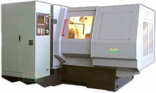
A BG500-D3 é uma máquina geradora de engrenagens cônicas espirais de última geração, essencial para a produção de engrenagens diferenciais de alto desempenho, coroas e pinhões. Utilizando o método de geração Face Hobbing (corte por faceamento), esta centro de usinagem CNC garante máxima precisão (repetibilidade de 0.005mm) e rugosidade superficial superior. Projetada para usinagem completa (desbaste e acabamento) em uma única fixação, sua estrutura rígida em fundição melhora a estabilidade e vida útil da ferramenta. Configurações incluem sistema automático de troca de paletes e carregador automático de engrenagens. Parâmetros-chave: diâmetro máximo da engrenagem Ø500mm, módulo máximo 12mm. Ideal para setores automotivo, aeroespacial, agrícola e de transmissões industriais. Sinônimos: Máquina para fabricar engrenagens cônicas, fresadora de engrenagens espirais, equipamento para usinagem de coroa e pinhão. Benefícios: Alta produtividade, confiabilidade alemã, manutenção simplificada, ciclo de vida estendido.
Ang BG500-D3 ay isang de-kalidad na spiral bevel gear generating machine na ginagamit para sa precision machining ng mga spiral bevel gear tulad ng mga differential gear, ring gear, at pinion. Gumagamit ito ng advanced na Face Hobbing process at closed-loop CNC control para sa sobrang tumpak (repeatability: 0.005mm) at makinis na finish. Key feature nito: kaya ang roughing at finishing sa iisang setup, malaking tipid sa oras. Matibay ang cast iron structure nito para sa matagal na gamit at mataas na rigidity. Pwedeng lagyan ng automatic pallet changer at gear loader. Mga specs: max gear diameter na 500mm, max module na 12mm. Pangunahing gamit sa automotive sector (lalo na sa paggawa ng mga gear para sa kotse, trak, e-bike), aerospace, heavy equipment, at industrial machinery. Kilala rin bilang: Makina ng spiral bevel gear, CNC gear cutting machine para sa mga kono. Mga pakinabang: Mataas na kahusayan, mababang maintenance cost, matibay na performance, user-friendly interface, mabilis na ROI.
La BG500-D3 è una fresatrice generatrice per ruote coniche a dentatura spirale ad altissima precisione, progettata per la produzione di ingranaggi conici differenziali, corone e pignoni. Sfrutta la tecnologia di taglio Face Hobbing con controllo CNC ad anello chiuso, garantendo ripetibilità di 0.005mm e finiture superficiali eccellenti. Eccellenza nell'utensileria: completa sgrossatura e finitura in un'unica bloccatura, aumentando drasticamente l'efficienza. La struttura portante in ghisa conferisce rigidità e assorbimento delle vibrazioni. Opzioni: cambio pallet automatico e caricatore ingranaggi. Specifiche tecniche: diametro max ingranaggio 500mm, modulo max 12. Settori chiave: automotive (assi, differenziali), aerospaziale, macchine agricole, energia. Conosciuta anche come: macchina per dentatura conica spirale, generatrice a CNC per ingranaggi conici. Vantaggi: Massima affidabilità, produttività elevatissima, manutenzione ridotta, precisione costante nel tempo, investimento sicuro per officine meccaniche specializzate.
BG500-D3, spiral konik dişli üretim makinesi olarak, yüksek hassasiyetli diferansiyel dişlileri, taç dişliler ve pinyonların imalatı için endüstriyel çözümdür. Yüzey Hoblamalı (Face Hobbing) kesme teknolojisi ve kapalı döngü CNC kontrol ile 0.005mm tekrarlanabilir hassasiyet sunar. Ana avantaj: tek bağlamada hem kaba hem de finiş işleme, zaman kazandırır. Güçlü döküm gövde titreşimi azaltır, takım ömrünü uzatır. Opsiyonel: otomatik palet değiştirici, dişli yükleyici. Temel parametreler: maks. dişli çapı 500mm, maks. modül 12. Otomotiv (araba dişlileri, kamyon aksları), havacılık, tarım makineleri ve endüstriyel aktarma organları için idealdir. Eşanlamlılar: Spiral konik dişli açma tezgahı, CNC konik dişli freze makinesi. Avantajlar: Yüksek verimlilik, Alman mühendislik kalitesi, düşük arıza oranı, kolay operasyon, uzun servis ömrü ile maliyet etkin üretim.
La BG500-D3 est une machine à tailler les engrenages coniques spirales de précision, indispensable pour la fabrication d'engrenages différentiels, de couronnes et de pignons de haute gamme. Elle emploie la technologie de taille par taillage de face (Face Hobbing) avec commande CNC en boucle fermée, assurant une répétabilité de 0.005mm et une excellente finition de surface. Atout majeur : ébauche et finition en une seule mise en position, optimisant le temps de cycle. Sa structure robuste en fonte minimise les vibrations et améliore la durée de vie de l'outil. Options : changeur de palettes automatique, chargeur automatique de pièces. Caractéristiques : diamètre max. de l'engrenage 500mm, module max. 12. Domaines clés : automobile (essieux, transmissions), aérospatiale, machines agricoles, énergie. Aussi appelée : Fraiseuse à engrenages coniques spirales, machine à générer les engrenages coniques. Avantages : Productivité exceptionnelle, fiabilité allemande, maintenance simplifiée, précision inégalée et conception ergonomique pour un retour sur investissement rapide.
آلة BG500-D3 هي ماكينة تشكيل تروس مخروطية حلزونية فائقة الدقة، مصممة لإنتاج تروس التفاضل (تروس دفرنس)، التروس التاجية (الكراون ويل)، والبنيونات. تستخدم تقنية القطع الوجهي (Face Hobbing) مع تحكم CNC بنظام حلقة مغلقة لضمان تكرارية 0.005 مم ونعومة سطح استثنائية. الميزة الفريدة: التشطيب والتجليخ الخشن في تثبيت واحد، مما يزيد الكفاءة. هيكل المصبوبة الحديدي يضمن متانة فائقة وامتصاص الاهتزازات. خيارات: نظام تبديل الباليتات الأوتوماتيكي، محمل التروس التلقائي. المواصفات: أقصى قطر ترس 500 مم، أقصى موديول 12. مجالات التطبيق: السيارات (المحاور، قطع الدفرنس)، الطيران، المعدات الزراعية، والطاقة. معروفة أيضًا باسم: ماكينة تفريز التروس المخروطية الحلزونية، ماكينة تشكيل تروس مخروطية CNC. المزايا: إنتاجية عالية، موثوقية ألمانية، صيانة منخفضة، دقة ثابتة، وواجهة مستخدم سهلة لتحقيق أفضل عائد على الاستثمار في مجال تشغيل المعادن.
Die BG500-D3 ist eine hochpräzise Spiral-Kegelrad-Generiermaschine für die Herstellung von Differentialgetrieben, Tellerrädern und Ritzeln. Sie arbeitet mit dem kontinuierlichen Taumel-Wälzfräsverfahren (Face Hobbing) und geschlossenem CNC-Regelkreis, garantiert Wiederholgenauigkeit von 0.005mm und erstklassige Oberflächengüte. Schlüsselvorteil: Schrupp- und Schlichtbearbeitung in einem Spannvorgang (One-Setup-Technologie), maximiert Durchsatz. Das massive Gussbett gewährleistet optimale Schwingungsdämpfung und Standzeitverlängerung der Werkzeuge. Optionen: Automatischer Palettenwechsler (APC), automatischer Teilelader. Kenndaten: Max. Werkstückdurchmesser 500mm, max. Modul 12. Kernbranchen: Automobilbau (Achsen, Antriebe), Luftfahrt, Landtechnik, Industriegetriebe. Auch bekannt als: Kegelradfräsmaschine, CNC-Kegelradgenerierer, Spiralbogenverzahnungsmaschine. Vorteile: Deutsche Ingenieurskunst für höchste Zuverlässigkeit (Made in Germany), hohe Wirtschaftlichkeit durch kurze Hauptzeiten, minimale Wartungskosten, robuste Konstruktion für die Serienfertigung präziser Zahnräder.
De BG500-D3 is een toonaangevende spiraalconische tandwielgenererende machine voor de productie van differentieeloverbrengingen, kroonwielen en pignons. Met geavanceerde Face Hobbing-technologie en gesloten CNC-regelkring biedt hij uitzonderlijke nauwkeurigheid (herhaalbaarheid 0.005mm) en superieure oppervlakteafwerking. Kernvoordeel: ruw- en afschroeiwerk in één opspanning, bespaart aanzienlijke bewerkingstijd. Het zware gietijzeren frame zorgt voor uitstekende demping en gereedschapsduur. Opties: automatische palletwisselaar, tandwielader. Specificaties: max. tandwieldiameter Ø500mm, max. module 12. Belangrijkste toepassingen: auto-industrie (differentieel, assen), lucht- en ruimtevaart, landbouwmachines, industriële transmissies. Ook bekend als: spiraalkegelwielfreesmachine, CNC kegelwielgenerator. Voordelen: Uitstekende betrouwbaarheid, hoge productiviteit, lage onderhoudsbehoefte, gebruiksvriendelijke bediening en kostenefficiënte productie van precisietandwielen voor veeleisende toepassingen.
BG500-D3 to zaawansowana obrabiarka do kół zębatych stożkowych o zazębieniu łukowym (spiral bevel), przeznaczona do produkcji precyzyjnych przekładni różnicowych, kół talerzowych i pinion. Wykorzystuje technologię Face Hobbing z zamkniętą pętlą sterowania CNC, gwarantując powtarzalność 0.005mm i doskonałą jakość powierzchni. Kluczowa zaleta: obróbka zgrubna i wykańczająca w jednym zamocowaniu (One-Setup), skracająca czas wykonania. Solidna, żeliwna konstrukcja zwiększa tłumienie drgań i trwałość narzędzi. Opcje: automatyczny zmieniacz palet (APC), podajnik kół. Parametry: maks. średnica koła 500mm, maks. moduł 12. Główne zastosowania: motoryzacja (przekładnie, osie), lotnictwo, maszyny rolnicze, przemysł. Znana również jako: frezarka do kół zębatych stożkowych, generator kół stożkowych CNC. Zalety: Najwyższa niezawodność (niemiecka jakość), wysoka wydajność produkcyjna, niskie koszty eksploatacji, precyzja w produkcji seryjnej, opłacalna inwestycja dla zakładów obróbczych.
BG500-D3 este o mașină de generat angrenaje conice spiralate de înaltă precizie, utilizată pentru fabricarea diferențialelor, a roților conice și a pinioanelor. Folosește tehnologia Face Hobbing cu control CNC în circuit închis, asigurând repetabilitate de 0.005mm și finisaje superficiale superioare. Principalul avantaj: prelucrarea de degroșare și finisare într-o singură prindere, economisind timp. Construcția robustă din fontă oferă amortizare vibrații și durată de viață a sculei extinsă. Opțiuni: schimbător automat de paleți, încărcător automat de roți dințate. Specificații: diametru maxim angrenaj 500mm, modul maxim 12. Domenii cheie: automotive (osii, transmisii), aerospațial, utilaje agricole, transmisii industriale. Cunoscută și ca: mașină de frezat angrenaje conice spiralate, generator CNC angrenaje conice. Avantaje: Fiabilitate germană de top, productivitate ridicată, costuri reduse de întreținere, precizie constantă și ușurință în operare pentru un ROI rapid în prelucrarea metalelor.
BG500-D3 spirális kúpkerék-generáló gépeink a legigényesebb fogaskerék-gyártási feladatokra készültek. Ez a csúcsminőségű gépi megoldás precíziós kúpkerék- és hipoid fogaskerekek gyártását teszi lehetővé CNC vezérlés segítségével. Fő jellemzői: max. 500 mm munkadarab-átmérő, IT5-es pontossági osztály, 6-12 modul tartomány. Siemens 840D sl CNC rendszerrel felszerelve, kiváló ismételhetőséget (±0.003 mm) és kiemelkedő felületi minőséget (Ra 0.8 μm) biztosít. Alkalmazása: járműipari differenciálművek, repülőgép-alkatrészek, nehézgépek nagy pontosságú fogaskerekei. Előnyök: rövid beállítási idő kis sorozatokhoz, kiváló kopásállóság, alacsony karbantartási igény. Fő komponensek: merev öntöttvas alap, precíziós golyósorsók, digitális szervómeghajtás, integrált mérési rendszer. Ideális megoldás "nagy pontosságú kúpfogaskerék-gyártásra", "hipoid fogaskerék-megmunkáló gép" vagy "CNC fogaskerék-hoborgépek" keresők számára. Fedezze fel a megbízható Fortunepacific megoldást!
Ο BG500-D3 είναι μια κορυφαία μηχανή γενεθλίων κωνικών γραναζιών σπειροειδούς δοντιού. Αποτελεί την ιδανική λύση για την κατασκευή υψηλής ακρίβειας κωνικών και υποειδών γραναζιών. Βασικές παράμετροι: μέγιστη διάμετρος τεμαχίου 500 mm, τάξη ακρίβειας IT5, εύρος δοντιού (module) 6-12. Εξοπλισμένη με σύστημα CNC Siemens 840D sl, εξασφαλίζει άψογη επαναληψιμότητα (±0,003 mm) και εξαιρετική ποιότητα επιφάνειας (Ra 0,8 μm). Περιλαμβάνει άκαμπτη βάση χυτοσιδήρου, ακριβείς μηχανισμούς τροφοδοσίας με σφαιρικούς βιδωτούς άξονες και ενσωματωμένο σύστημα μέτρησης. Εφαρμογές: αυτοκινητοβιομηχανία (διαφορικά), αεροδιαστημική, βαρύς μηχανολογικός εξοπλισμός. Πλεονεκτήματα: ταχύς χρόνος παραγωγής για μικρές σειρές, εξαιρετική αξιοπιστία, χαμηλό κόστος συντήρησης. Ιδανική για "μηχανήματα κατασκευής κωνικών γραναζιών υψηλής ακρίβειας", "σπειροειδή κωνικά γρανάζια" ή "σύγχρονα CNC μηχανήματα γραναζιών". Επιλέξτε την Fortunepacific για κορυφαία αποτελέσματα.
BG500-D3 je špičkový obráběcí stroj na výrobu kuželových ozubených kol se šroubovicovým ozubením. Tento CNC stroj zaručuje extrémní přesnost (třída IT5) při výrobě kuželových a hypoidních kol. Klíčové parametry: max. průměr obrobku 500 mm, modul 6-12, opakovatelnost ±0,003 mm. Vybaven řídicím systémem Siemens 840D sl, dosahuje vynikající jakosti povrchu (Ra 0,8 μm). Robustní litinová konstrukce, přesné kuličkové šrouby, digitální servopohony a integrovaný měřicí systém zajišťují dlouhou životnost a minimální údržbu. Aplikace: diferenciály v automobilovém průmyslu, letecké komponenty, těžká technika. Hlavní výhody: rychlé seřízení pro malé série, vysoká spolehlivost, nízké provozní náklady. Hledáte "vysokopřesné obrábění kuželových kol", "CNC stroj na výrobu hypoidních ozubených kol" nebo "moderní zařízení na výrobu ozubených kol"? BG500-D3 je optimální volba. Spolehněte se na Fortunepacific.
BG500-D3 е високоточна машина за нарязване на конични зъбни колела със спирални зъби. Този CNC стан е проектиран за производство на прецизни конични и хипоидни зъбни колела. Основни параметри: макс. диаметър на детайла 500 mm, клас на точност IT5, модул 6-12. Оборудван със системата Siemens 840D sl, осигурява изключителна повторяемост (±0,003 mm) и отлично качество на повърхността (Ra 0,8 μm). Здрава чугунена конструкция, прецизни водещи винтове, цифрови серво задвижвания и вградена измерителна система гарантират дълъг експлоатационен живот. Приложения: автомобилни диференциали, авиационни компоненти, тежка техника. Предимства: бързо пренастройване за малки серии, висока надеждност, ниски разходи за поддръжка. Търсите "машина за високоточни конични зъбни колела", "хипоидни зъбни колела CNC" или "модерно оборудване за зъбозарезване"? BG500-D3 е идеалното решение. Fortunepacific - гаранция за качество.
BG500-D3 је врхунска CNC машина за израду спиралних зупчаника. Ова прецизна опрема специјално је дизајнирана за производњу коничних и хипоидних зупчаника високе тачности (класа IT5). Кључни параметри: макс. пречник израђевине 500 mm, модул 6-12, понављивост ±0,003 mm. Опремљена системом Siemens 840D sl, постиже изузетан квалитет површине (Ra 0,8 μm). Робусна конструкција од сивог лива, прецизни куглични завојни органи, дигитални серво погони и интегрисани мерни систем обезбеђују дуговечност и минимално одржавање. Примена: аутомобилска диференцијална зупчаника, аеронаутички делови, тешка опрема. Предности: брзо припремање за мале серије, висока поузданост, ниски трошкови рада. Ако тражите "машине за прецизну обраду коничних зупчаника", "хипоидни зупчаници CNC" или "савремену опрему за израду зупчаника", BG500-D3 је идеалан избор. Изаберите Fortunepacific за квалитет.
BG500-D3 je špičkový obrábací stroj na výrobu kužeľových ozubených kolies so špirálovým ozubením. Toto CNC zariadenie zabezpečuje výnimočnú presnosť (trieda IT5) pri výrobe kužeľových a hypoidných kolies. Parametre: max. priemer obrobku 500 mm, modul 6-12, opakovateľnosť ±0,003 mm. Vybavené riadiacim systémom Siemens 840D sl, dosahuje vynikajúcu kvalitu povrchu (Ra 0,8 μm). Robustná konštrukcia z liatiny, presné guľkové skrutky, digitálne servopohony a integrovaný merací systém zaručujú dlhú životnosť a nízke náklady na údržbu. Aplikácie: diferenciály v automobilovom priemysle, letecké komponenty, ťažká technika. Výhody: rýchle nastavenie pre malé série, vysoká spoľahlivosť, efektívna prevádzka. Hľadáte "vysokopresné obrábanie kužeľových ozubených kolies", "CNC stroj na výrobu hypoidných kolies" alebo "moderné zariadenia na výrobu ozubených kolies"? BG500-D3 je optimálna voľba. Fortunepacific - spoľahlivosť v priemysle.
BG500-D3 je vrhunski stroj za izradu spiralnih zupčanika. Ova precizna CNC oprema namijenjena je proizvodnji konusnih i hipoidnih zupčanika visoke točnosti (razred IT5). Ključni parametri: max. promjer izratka 500 mm, modul 6-12, ponovljivost ±0,003 mm. Opremljen Siemens 840D sl sustavom, postiže izvrsnu kvalitetu površine (Ra 0,8 μm). Čvrsta konstrukcija od sivog lijeva, precizni kuglični vijci, digitalni servo pogoni i integrirani mjerni sustav osiguravaju dugotrajnost i minimalno održavanje. Primjena: diferencijali u automobilskoj industriji, zrakoplovni dijelovi, teška oprema. Prednosti: brzo postavljanje za male serije, visoka pouzdanost, niski troškovi rada. Ako tražite "strojeve za preciznu obradu konusnih zupčanika", "hipoidni zupčanici CNC" ili "suvremenu opremu za izradu zupčanika", BG500-D3 je idealan izbor. Fortunepacific jamči vrhunsku kvalitetu.
BG500-D3 je vrhunska obdelovalna naprava za izdelavo spiralnih stožčastih zobnikov. Ta visoko natančen CNC stroj je namenjen izdelavi stožčastih in hipoidnih zobnikov (natančnost IT5). Ključni parametri: max. premer obdelovanca 500 mm, modul 6-12, ponovljivost ±0,003 mm. Opremljen s sistemom Siemens 840D sl, zagotavlja odlično kakovost površine (Ra 0,8 μm). Trdna konstrukcija iz litega železa, natančni vijačni mehanizmi s krogličnim ležajem, digitalni servo pogoni in vgrajen merilni sistem zagotavljajo dolgo življenjsko dobo in nizke stroške vzdrževanja. Uporaba: avtomobilske diferenčale, letalski deli, težka oprema. Prednosti: hitra priprava za majhne serije, visoka zanesljivost, učinkovito delovanje. Če iščete "naprave za visoko natančno obdelavo stožčastih zobnikov", "CNC stroj za hipoidne zobnike" ali "moderno opremo za izdelavo zobnikov", je BG500-D3 idealna izbira. Izberite Fortunepacific za kakovost.
BG500-D3 — високоточний верстат для нарізування спіральних конічних зубчастих коліс. Цей ЧПК верстат забезпечує виняткову точність (клас IT5) при виробництві конічних та гіпоїдних коліс. Основні параметри: макс. діаметр заготівлі 500 мм, модуль 6-12, повторюваність ±0,003 мм. Обладнаний системою Siemens 840D sl, досягає чудової якості поверхні (Ra 0,8 мкм). Міцна чавунна конструкція, прецизійні кулькові гвинти, цифрові сервоприводи та вбудована вимірювальна система гарантують довговічність та низькі витрати на обслуговування. Застосування: автомобільні диференціали, авіаційні компоненти, важке обладнання. Переваги: швидке переналагодження для дрібних серій, висока надійність, ефективна робота. Шукаєте "верстати для високоточної обробки конічних зубчастих коліс", "ЧПК верстат для гіпоїдних коліс" чи "сучасне обладнання для зуборізання"? BG500-D3 — оптимальний вибір. Оберіть Fortunepacific для якості.