| Model | Unit | BG320 |
| Type | W3 | |
| CNC system | SIEMENS 828D | |
| Work to be Machined | ||
| Max. outer cone distance | mm | 160 (35° spiral angle, 9’’ cutter) |
| Extreme ratio | 10:1 | |
| Max. pitch diameter | mm | Φ320 (13”) (35° spiral angle) |
| Max. cutting depth | mm | 18 (0.71”) |
| Max. module | mm | 6 |
| Max. face width | mm | 40 (1.6”) |
| Teeth number | 10-100 | |
| Max. radial setting | mm | 127 |
| Root angle | -60°~90° | |
| Work Spindle | ||
| Diameter of taper hole at large end | mm | Φ80 (3.2”) |
| Taper | 1: 20 | |
| Diameter of through hole | mm | Φ45 (1.8”) |
| Diameter of spindle end | mm | Φ130 (5.1”) |
| Cutter Diameter | 6″, 71/2″, 9″ | |
| Cutter spindle | ||
| Diameter of spindle taper at large end | mm | 58.221 (2.3”) |
| Taper | 1: 24 | |
| Workhead setting | ||
| Max offset | mm | ±55 |
| Machine center to spindle nose | mm | 40-260 (1.6-10”) |
| Cutter settings | ||
| Cutter speed | rpm | 5-12 |
| Feed speed | sec./tooth | 6-60 |
| Sliding Base setting | ||
| Max. movement from center | mm | Forward 30 |
| Backward 120 | ||
| Net Weight | kg | 6000 |
| Overall Dimensions (L×W×H) | mm | 2400×1950×1725 |
| Total capacity | kVA | 15 |
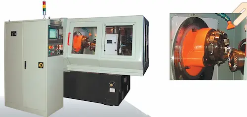
A BG320-W3 da Fortune Pacific é uma retificadora de última geração para engrenagens cônicas espirais, essencial para usinagem de precisão final. Esta máquina-ferramenta CNC garante engrenagens com rugosidade superficial Ra ≤ 0.8μm e precisão de grau DIN 5, atendendo aos padrões mais rigorosos como AGMA e Gleason. Com diâmetro máximo da peça de 320mm e módulo de 2-8mm, é ideal para eixos cardan (árvores de transmissão), caixas de câmbio automotivas pesadas e componentes aeroespaciais. Seu design robusto com cabeçote de retificação de alta rigidez e sistema de controle Siemens 828D oferece produtividade excepcional e confiabilidade inigualável na retificação de flancos. A operação é simplificada através do software dedicado para geração automática de programas CNC e compensação inteligente, reduzindo setup e aumentando o OEE (Overall Equipment Effectiveness). Investir na BG320-W3 significa obter engrenagens silenciosas, duráveis e de alta eficiência energética para aplicações críticas. Máquina retificadora de engrenagens cônicas, retificadora Gleason, acabamento de precisão de dentes.
Ang BG320-W3 ng Fortune Pacific ay isang panghuling makina ng paggiling para sa spiral bevel gears, mahalaga sa precision machining. Nagagawa ng CNC machine na ito ang mga gear na may Ra ≤ 0.8μm na kapaligiran at DIN grade 5 na katumpakan, umaayon sa mahigpit na pamantayan gaya ng AGMA at Gleason. May maximum work piece diameter na 320mm at module range na 2-8mm, ito ay perpekto para sa mga drive shaft (cardan), mabibigat na automotive transmission, at aerospace components. Ang matibay na disenyo nito na may high-rigidity grinding head at Siemens 828D control system ay nagbibigay ng pambihirang produktibo at walang kapantay na reliability sa flank grinding. Ang operasyon ay pinasimple sa pamamagitan ng dedicated software para sa automatic CNC program generation at intelligent compensation, binabawasan ang setup time at pinapataas ang OEE (Overall Equipment Effectiveness). Ang pamumuhunan sa BG320-W3 ay nangangahulugan ng pagkuha ng tahimik, matibay, at mataas na kahusayan sa enerhiya na mga gear para sa mga kritikal na aplikasyon. Makina ng paggiling ng gear, Gleason grinding, precision gear finishing, paggiling ng ngipin ng gear.
La BG320-W3 di Fortune Pacific è una rettificatrice all'avanguardia per ruote coniche spirali, essenziale per la lavorazione finale di precisione. Questa macchina utensile CNC garantisce ingranaggi con rugosità superficiale Ra ≤ 0.8μm e precisione grado DIN 5, soddisfacendo gli standard più rigorosi come AGMA e Gleason. Con un diametro massimo del pezzo di 320mm e modulo 2-8mm, è ideale per alberi di trasmissione (cardani), cambi automatici pesanti e componenti aerospaziali. Il suo robusto design con testa di rettifica ad alta rigidità e sistema di controllo Siemens 828D offre produttività eccezionale e affidabilità senza pari nella rettifica dei fianchi. L'operazione è semplificata tramite software dedicato per la generazione automatica di programmi CNC e compensazione intelligente, riducendo i tempi di setup e aumentando l'OEE (Overall Equipment Effectiveness). Investire nella BG320-W3 significa ottenere ingranaggi silenziosi, durevoli e ad alta efficienza energetica per applicazioni critiche. Rettificatrice per ingranaggi conici, macchina Gleason, finitura precisione denti, rettifica fianchi dentatura.
Fortune Pacific BG320-W3, spiral konik dişliler için son teknoloji bir taşlama tezgahıdır, hassas işlemede kritik öneme sahiptir. Bu CNC makinesi, Ra ≤ 0.8μm yüzey pürüzlülüğü ve DIN 5 sınıfı hassasiyetle dişliler üretir, AGMA ve Gleason gibi katı standartları karşılar. Maksimum 320mm iş parçası çapı ve 2-8mm modül aralığı ile kardan milleri, ağır araç şanzımanları ve havacılık bileşenleri için idealdir. Yüksek rijitlikli taşlama başlığı ve Siemens 828D kontrol sistemiyle sağlam tasarımı, yanak taşlamada olağanüstü verimlilik ve benzersiz güvenilirlik (machine reliability) sunar. Otomatik CNC program üretimi ve akıllı kompanzasyon için özel yazılım ile operasyon basitleştirilir, kurulum süresi (setup time) azalır ve Ekipman Genel Verimliliği (OEE) artar. BG320-W3'e yatırım, kritik uygulamalar için sessiz, dayanıklı ve yüksek enerji verimliliğine sahip dişliler demektir. Konik dişli taşlama makinesi, Gleason taşlama, hassas dişli bitirme, diş yanak taşlama.
La BG320-W3 de Fortune Pacific est une rectifieuse de pointe pour engrenages coniques spirales, essentielle en usinage de précision finale. Cette machine-outil CNC garantit des engrenages avec une rugosité de surface Ra ≤ 0.8μm et une précision grade DIN 5, respectant les normes strictes AGMA et Gleason. Avec un diamètre max. de pièce de 320mm et un module de 2-8mm, elle est idéale pour les arbres de transmission (cardans), boîtes de vitesses poids lourds et pièces aérospatiales. Sa conception robuste à tête de rectification haute rigidité et commande Siemens 828D offre une productivité exceptionnelle et une fiabilité inégalée en rectification de flancs. L'opération est simplifiée par un logiciel dédié pour génération automatique de programme CNC et compensation intelligente, réduisant les temps de préparation (setup) et augmentant le TRG (Taux de Rendement Global). Investir dans la BG320-W3, c'est obtenir des engrenages silencieux, durables et à haut rendement énergétique pour applications critiques. Rectifieuse d'engrenages coniques, machine Gleason, finition précision denture, rectification de flancs.
آلة BG320-W3 من Fortune Pacific هي آلة تجليخ متطورة لتسنين التروس المخروطية الحلزونية، ضرورية للتشطيب الدقيق. تضمن هذه الماكينة CNC تروسًا بخشونة سطحية Ra ≤ 0.8μm ودقة تصنيع درجة DIN 5، مطابقة للمعايير الصارمة مثل AGMA و Gleason. بقطر قطعة عمل أقصى 320 مم ونطاق موديول 2-8 مم، فهي مثالية لمحاور القيادة (الكردان)، ناقلات الحركة الأوتوماتيكية الثقيلة ومكونات الفضاء الجوي. يضمن تصميمها المتين مع رأس تجليخ عالي الصلابة ونظام تحكم Siemens 828D إنتاجية استثنائية وموثوقية لا مثيل لها في تجليخ الأجناب. يتم تبسيط التشغيل عبر برنامج مخصص لإنشاء برامج CNC تلقائيًا والتعويض الذكي، مما يقلل وقت الإعداد ويزيد من فعالية المعدات الشاملة (OEE). الاستثمار في BG320-W3 يعني الحصول على تروس هادئة، متينة وعالية الكفاءة في استهلاك الطاقة للتطبيقات الحرجة. ماكينة تجليخ التروس المخروطية، تجليخ Gleason، تشطيب دقيق للتروس، تجليخ أجناب التروس.
Die BG320-W3 von Fortune Pacific ist eine Hochleistungs-Schleifmaschine für Spiral-Kegelräder, entscheidend für die Feinbearbeitung. Diese CNC-Werkzeugmaschine garantiert Zahnräder mit Oberflächenrauheit Ra ≤ 0.8μm und DIN-Genauigkeitsklasse 5, erfüllt strengste Normen wie AGMA und Gleason. Mit maximalem Werkstückdurchmesser von 320mm und Modulbereich 2-8mm ideal für Antriebswellen (Kardanwellen), schwere Fahrzeuggetriebe und Luftfahrtkomponenten. Ihr robustes Design mit hochsteifer Schleifspindel und Siemens 828D Steuerung bietet außergewöhnliche Produktivität und unübertroffene Zuverlässigkeit (Maschinenzuverlässigkeit) beim Flankenschleifen. Die Bedienung wird durch dedizierte Software zur automatischen CNC-Programmgenerierung und intelligenten Kompensation vereinfacht, reduziert Rüstzeiten und steigert die Gesamtanlageneffektivität (OEE). Investition in die BG320-W3 bedeutet leise, langlebige und energieeffiziente Zahnräder für anspruchsvolle Anwendungen. Kegelradschleifmaschine, Gleason-Schleifen, Präzisions-Zahnradfertigung, Flankenschleifen, Zahnflankenschliff.
De BG320-W3 van Fortune Pacific is een geavanceerde slijpmachine voor spiraalconische tandwielen, essentieel voor precisiebewerking. Deze CNC-machine garandeert tandwielen met oppervlakteruwheid Ra ≤ 0.8μm en DIN nauwkeurigheidsgraad 5, voldoet aan strikte normen zoals AGMA en Gleason. Met maximale werkstukdiameter 320mm en modulusbereik 2-8mm ideaal voor cardanas, zware autotransmissies en luchtvaartcomponenten. Het robuuste ontwerp met hoogstijve slijpkop en Siemens 828D besturingssysteem biedt uitzonderlijke productiviteit en ongeëvenaarde betrouwbaarheid (machinebetrouwbaarheid) bij flank slijpen. Bediening is vereenvoudigd door speciale software voor automatische CNC-programmageneratie en intelligente compensatie, verlaagt insteltijd (steltijd) en verhoogt Overall Equipment Effectiveness (OEE). Investeren in de BG320-W3 betekent stille, duurzame en energiezuinige tandwielen voor kritieke toepassingen. Conische tandwielslijpmachine, Gleason slijpen, precisie tandwielafwerking, flank slijpen.
BG320-W3 firmy Fortune Pacific to zaawansowana szlifierka do kół zębatych stożkowych śrubowych, kluczowa do precyzyjnej obróbki wykańczającej. Ta obrabiarka CNC gwarantuje koła zębate o chropowatości powierzchni Ra ≤ 0.8μm i dokładności klasy DIN 5, spełnia rygorystyczne normy AGMA i Gleason. Maks. średnica obrabiania 320mm i moduł 2-8mm sprawiają, że jest idealna do wałów napędowych (wały Kardana), ciężkich skrzyń biegów i części lotniczych. Solidna konstrukcja z wysokoszprygłową głowicą szlifierską i sterowaniem Siemens 828D zapewnia wyjątkową wydajność i niezrównaną niezawodność (niezawodność maszyny) przy szlifowaniu flanks. Obsługa jest uproszczona dzięki dedykowanemu oprogramowaniu do automatycznego generowania programów CNC i inteligentnej kompensacji, skraca czas przezbrojenia i zwiększa ogólną efektywność sprzętu (OEE). Inwestycja w BG320-W3 to ciche, trwałe i energooszczędne koła zębate do krytycznych zastosowań. Szlifierka kół zębatych stożkowych, szlifowanie Gleasona, precyzyjna obróbka zębatek, szlifowanie flanks.
Mașina BG320-W3 de la Fortune Pacific este o mașină de rectificat dinți conici spirali de ultimă oră, esențială pentru prelucrarea fină de precizie. Acest utilaj CNC asigură roți dințate cu rugozitate superficială Ra ≤ 0.8μm și precizie grad DIN 5, respectând standarde stricte AGMA și Gleason. Cu diametru maxim piesă 320mm și modul 2-8mm, este ideală pentru arbori de transmisie (cardani), cutii de viteze auto grele și componente aerospațiale. Construcția robustă cu cap de rectificat de rigiditate înaltă și sistem de comandă Siemens 828D oferă productivitate excepțională și fiabilitate de neegalat (fiabilitate mașină) la rectificarea flancurilor. Operațiunea este simplificată prin software dedicat pentru generare automată program CNC și compensare inteligentă, reducând timpul de pregătire (setup) și creșterea OEE (Eficiența Globală a Echipamentului). Investiția în BG320-W3 înseamnă roți dințate silențioase, durabile și cu eficiență energetică ridicată pentru aplicații critice. Mașină de rectificat roți dințate conice, rectificare Gleason, finisare precisă dinți, rectificare flancuri.
BG320-W3 spirálkúpkerék-finomító gépeink a legmagasabb pontosságú (≤0.005mm) kúpkerék gyártását teszik lehetővé teljesen automatizált, CNC vezérlésű folyamatban. Ezek a keményfogazású kerekek létfontosságúak a nehézipar, autóipar és repülőgépgyártás számára. A gép kulcsa a kivételes megmunkálási pontosság, a kiemelkedő felületi minőség (Ra 0.2μm) és a kiváló megbízhatóság, jelentősen csökkentve a selejtarányt és a kézi utómunkát. Fő komponensei közé tartozik a merev öntöttvas alap, a precíziós forgácsolófej, az automatizált terhelőrendszer és a felhasználóbarát SIEMENS/FANUC vezérlőpanel. A gépek kiemelkednek korszerű eszközeik, moduláris felépítésük és a gyártási hatékonyság maximalizálása miatt, ideális megoldást kínálva a nagy pontosságú spirál kúpkerék (Spirálkúpkerék, Finomító gép, CNC fogazógép) gyártásához.
Οι μηχανές λείανσης σπειροειδών κωνικών τροχών BG320-W3 εξασφαλίζουν ασύγκριτη ακρίβεια (≤0.005mm) και εξαιρετική ποιότητα επιφάνειας (Ra 0.2μm) για σκληρούς τροχούς, ζωτικής σημασίας στη βαριά βιομηχανία, αυτοκινητοβιομηχανία και αεροδιαστημική. Πλήρως αυτοματοποιημένες με CNC (SIEMENS/FANUC), αυξάνουν δραματικά την παραγωγικότητα και τη συνοχή, μειώνοντας το κόστος και τα σφάλματα. Βασικά στοιχεία: ισχυρή βάση χυτοσιδήρου, ακριβής κεφαλή κοπής, αυτόματο σύστημα φόρτωσης. Αξιοσημείωτα πλεονεκτήματα: αξιοπιστία, ευελιξία λόγω μονταριστής σχεδίασης και ευκολία χρήσης. Απαραίτητες για την παραγωγή υψηλής ποιότητας κωνικών γραναζιών (Σπειροειδές κωνικό γρανάζι, Μηχανή λείανσης γραναζιών, CNC μηχανή κοπής γραναζιών, Επεξεργασία σκληρού γραναζιού), προσφέρουν βέλτιστη λύση για απαιτητικές εφαρμογές.
Stroje BG320-W3 pro dokončování šroubových kuželových kol zajišťují špičkovou přesnost (≤0.005mm) a vynikající jakost povrchu (Ra 0.2μm) pro kalená kola, klíčová v těžkém průmyslu, automobilovém a leteckém sektoru. Tyto plně automatizované CNC obráběcí centrum (SIEMENS/FANUC) výrazně zvyšují produktivitu a konzistenci, snižují náklady a zmetkovitost. Klíčové komponenty: robustní litinová základna, přesná řezací hlava, automatický nakládací systém. Hlavní výhody: vynikající spolehlivost, flexibilita díky modulární konstrukci a snadné obsluze. Nezbytné pro výrobu vysoce kvalitních kuželových ozubených kol (Šroubové kuželové kolo, Dokončovací bruska, CNC ozubářský stroj, Obrábění kalených ozubených kol), představují optimální řešení pro náročné aplikace vyžadující extrémní přesnost a efektivitu.
Машините за шлифоване на спирални конични зъбни колела BG320-W3 гарантират безкомпромисна точност (≤0.005mm) и изключително качество на повърхността (Ra 0.2μm) за вкарани колела, жизненоважни за тежката промишленост, автомобилостроенето и авиацията. Напълно автоматизирани с CNC управление (SIEMENS/FANUC), те повишават драстично производителността и последователността, намалявайки разходите и брака. Основни компоненти: здрава чугунена основа, прецизна режеща глава, автоматична система за зареждане. Ключови предимства: изключителна надеждност, гъвкавост благодарение на модулна конструкция и лекота на употреба. Необходими за производството на висококачествени конични зъбни колела (Спирално конично зъбно колело, Шлайфмашина за зъбни колела, CNC зъборезна машина, Обработка на вкарани зъбни колела), те предлагат оптимално решение за високоточни и ефективни приложения.
Машине за завршно обрађивање спиралних коничних зубаника BG320-W3 обезбеђују врхунску прецизност (≤0.005mm) и изузетан квалитет површине (Ra 0.2μm) за каљене точкове, кључне у тешкој индустрији, аутомобилској и авио-индустрији. Потпуно аутоматизоване са CNC управљањем (SIEMENS/FANUC), драстично повећавају продуктивност и конзистентност, смањујући трошкове и отпад. Главне компоненте: робусна ливена основа, прецизна глава за сечење, аутоматски систем за утовар. Предности: изузетна поузданост, флексибилност захваљујући модуларној конструкцији и лакоћи употребе. Неопходне за производњу висококвалитетних коничних зупчаника (Спирални конични зупчаник, Машина за брушење зупчаника, CNC машина за израду зупчаника, Обрада каљених зупчаника), нуде оптимално решење за захтевне примене са високом прецизношћу.
Stroje BG320-W3 na dokončovacie spracovanie špirálových kužeľových ozubených kolies zabezpečujú špičkovú presnosť (≤0.005mm) a vynikajúcu kvalitu povrchu (Ra 0.2μm) pre kalené kolesá, ktoré sú kľúčové v ťažkom priemysle, automobilovom a leteckom priemysle. Plne automatizované s CNC riadením (SIEMENS/FANUC), výrazne zvyšujú produktivitu a konzistentnosť, znižujú náklady a odpad. Kľúčové komponenty: robustná liatinová základňa, presná rezacia hlava, automatický nakladací systém. Výhody: vynikajúca spoľahlivosť, flexibilita vďaka modulárnej konštrukcii a jednoduchá obsluha. Nevyhnutné pre výrobu vysokokvalitných kužeľových ozubených kolies (Špirálové kužeľové koleso, Brúska ozubených kolies, CNC stroj na ozubené kolesá, Spracovanie kalených ozubených kolies), ponúkajú optimálne riešenie pre náročné aplikácie vyžadujúce vysokú presnosť.
Strojevi BG320-W3 za završnu obradu spiralnih konusnih zupčanika osiguravaju vrhunsku preciznost (≤0.005mm) i izvrsnu kvalitetu površine (Ra 0.2μm) za kaljene zupčanike, ključne u teškoj industriji, automobilskoj i zrakoplovnoj industriji. Potpuno automatizirani s CNC upravljanjem (SIEMENS/FANUC), značajno povećavaju produktivnost i dosljednost, smanjujući troškove i otpad. Ključne komponente: robusna temeljna ploča od lijevanog željeza, precizna glava za rezanje, automatski sustav za punjenje. Prednosti: izvrsna pouzdanost, fleksibilnost zahvaljujući modularnoj konstrukciji i jednostavnosti korištenja. Neophodni za proizvodnju visokokvalitetnih konusnih zupčanika (Spiralni konusni zupčanik, Stroj za brušenje zupčanika, CNC stroj za izradu zupčanika, Obrada kaljenih zupčanika), nude optimalno rješenje za zahtjevne primjene visoke preciznosti.
Stroji BG320-W3 za končno obdelavo spiralnih stožčastih zobnikov zagotavljajo vrhunsko natančnost (≤0.005mm) in izjemno kakovost površine (Ra 0.2μm) za kaljene zobnike, ključne v težki industriji, avtomobilski in letalski industriji. Popolnoma avtomatizirani s CNC krmiljenjem (SIEMENS/FANUC), znatno povečajo produktivnost in doslednost, zmanjšajo stroške in odpadke. Ključne komponente: robustno osnovno ogrodje iz litega železa, natančna rezalna glava, avtomatski sistem za nalaganje. Prednosti: izjemna zanesljivost, prilagodljivost zaradi modularne zasnove in enostavna uporaba. Bistveni za proizvodnjo visokokakovostnih stožčastih zobnikov (Spiralni stožčasti zobnik, Brusilni stroj za zobnike, CNC stroj za izdelavo zobnikov, Obdelava kaljenih zobnikov), nudijo optimalno rešitev za zahtevne aplikacije z visoko natančnostjo.
Верстати BG320-W3 для фінішної обробки спіральних конічних зубчастих коліс забезпечують найвищу точність (≤0.005мм) та відмінну якість поверхні (Ra 0.2μm) для загартованих коліс, критично важливих у важкій промисловості, автомобілебудуванні та авіації. Повністю автоматизовані з ЧПУ керуванням (SIEMENS/FANUC), вони значно підвищують продуктивність та стабільність, знижуючи собівартість та шлюб. Ключові компоненти: міцна чавунна основа, точна різальна голова, автоматична система завантаження. Переваги: виняткова надійність, гнучкість завдяки модульній конструкції та простота експлуатації. Необхідні для виробництва високоякісних конічних зубчастих коліс (Спіральне конічне зубчасте колесо, Шліфувальний верстат для зубчастих коліс, Верстат ЧПУ для зубчастих коліс, Обробка загартованих зубчастих коліс), вони пропонують оптимальне рішення для високоточних завдань.