| Item | ST635SC |
| Capability | |
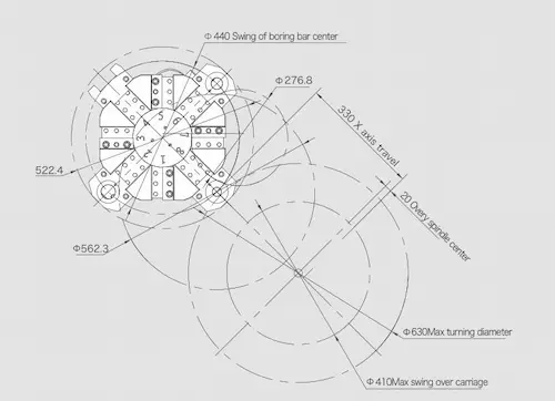
| Max. swing over bed | Φ650mm(25.6’’) |
| Max. swing over saddle | Φ410mm(16.1’’) |
| Max. turning diameter | Φ630mm(24.8’’) |
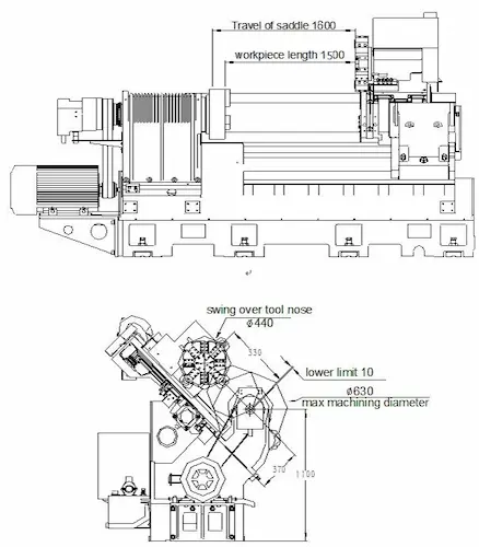
| Max. machining length | 1500mm(59.0’’) |
| Bar capacity | Φ74mm(2.9’’) (when equipped with 12’’ hydraulic hollow chuck) |
| Spindle | |
| Spindle motor output power | 15/18.5Kw(inverter) |
| Spindle nose | A2-8 |
| Max. spindle speed | 2000rpm |
| Spindle bore diameter | Φ87mm(3.4’’) |
| Chuck size | 12” inch (Hydraulic solid) |
| X/Z axis travel | |
| X-axis travel | 330mm(13.0’’) |
| Z-axis travel | 1600mm(63.0’’) |
| Rapid traverse of X-axis | 8m/min(314 IPM) |
| Rapid traverse of Z-axis | 12m/min(472 IPM) |
| Turret | |
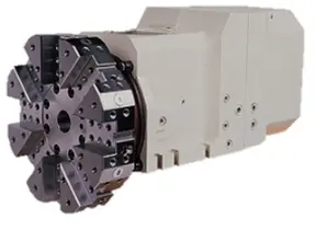
| Number of tool | 8 |
| Turing tool size | 32x25mm |
| Max. boring tool diameter | Φ50mm |
| Tailstock | |
| Hydraulic tailstock center | MT5 |
| Quill diameter | 130mm |
| Quill travel | 100mm |
| Accuracy | |
| Positioning accuracy (X/Z-axis) | 0.012/0.014mm |
| Repeatability (X/Z-axis) | 0.006/0.008mm |
| Others | |
| Power capacity | 35 kVA |
| Machine dimension (L x W x H) | 5810x1975x2145mm |
| Net weight | 8000kg |
| Item 01 | Descriptions | |
| 01.01 | FANUC Oi TF | |
| 01.02 | 2000rpm belt drive spindle (Frequency conversion motor) | |
| 01.03 | 8 position hydraulic turret (refer to follow turret information) | |
| 01.04 | 12’’ solid hydraulic chuck with 1 set soft jaw | |
| 01.05 | Solid hydraulic cylinder | |
| 01.06 | Hydraulic tailstock | |
| 01.07 | Hydraulic system | |
| 01.08 | Air conditioner of electrical cabinet | |
| 01.09 | Auto chip conveyer chip chart | |
| 01.10 | Auto oil lubrication system | |
| 01.11 | Tri-color light | |
| 01.12 | Air gun | |
| 01.13 | Door lock switch | |
| 01.14 | Lighting lamp | |
| 01.15 | Full enclosure splash guard | |
| 01.16 | Telescopic covers |
| Item 02 | Descriptions | Note |
| 02.01 | SIEMENS 828D 240 | |
| 02.02 | Shop turn | |
| 02.03 | 18.5/22KW inverter spindle motor | |
| 02.04 | 22/26KW inverter spindle motor | |
| 02.05 | FANUC β servo spindle motor, 15/18.5kw | |
| 02.06 | FANUC 0I TF 1 with α servo spindle motor, 22/26kw | |
| 02.07 | SIEMENS servo spindle motor, 17KW | |
| 02.08 | Double speed spindle motor, 15/18.5kw | |
| 02.09 | Manual guide 0I | |
| 02.10 | Manual guide I | for FANUC TF1 |
| 02.11 | DATA SERVE 2GB | for FANUC TF1 |
| 02.12 | Tool setter RENISHAW | Manual plug type |
| 02.13 | Tool setter RENISHAW | Auto swing type |
| 02.14 | Auto parts catcher | Swing type |
| 02.15 | Memory of FANUC controller 2MB | |
| 02.16 | M30 auto power off | |
| 02.17 | Scraping chip conveyor for aluminums cutting | |
| 02.18 | Magnetic chip conveyor | |
| 02.19 | Oil mister collector | |
| 02.20 | Auto-door (pneumatic control) | |
| 02.21 | 2 year FANUC warranty | |
| 02.22 | 2 year Siemens warranty | |
| 02.23 | CE standard | |
| 02.24 | 380V 50HZ/415V 50 HZ /220V 60 HZ | |
| 02.25 | Transformer | |
| 02.26 | Voltage stabilizer | |
| 02.27 | Grease lubrication instead of oil | |
| 02.28 | Bar feeder interface | |
| 02.29 | Auto bar feeder 26mm diameter, 3000mm length | |
| 02.30 | Auto bar feeder 65mm diameter, 1500mm length, DH65L | |
| 02.31 | Auto bar feeder 65mm diameter, 1250mm length, DH65 | |
| 02.32 | Hydraulic spring clamping tail stock | Tail stock body clamp by hydraulic spring |
| 02.33 | Fixed center, M#5 for standard tail stock | |
| 02.34 | Live center M#5 | For option tail stock with live center |
| 02.35 | U drilling tool holder with coolant through 1.5bar/10 bar | |
| 02.36 | Boring tool holder | |
| 02.37 | Boring tool holder sleeve (25, 32, 40) | |
| 02.38 | End face turning tool holder | |
| 02.39 | End face turning tool holder installation block | |
| 02.40 | 8 position servo turret, 32X25, 100mm center height | LioShing, |
| 02.41 | 12 position servo turret, 25X25, 100mm center height | LioShing, |
| 02.42 | 12 position hydraulic turret, 25x25, 100mm center height | LioShing, working range change |
| 02.43 | 12 position hydraulic turret, 32X32, 125mm center height | LioShing, working range change |
| 02.44 | Hydraulic steady rest (8—70mm) | Huanke |
| 02.45 | Hydraulic steady rest (20—120mm) | Huanke |
| 02.46 | Hydraulic steady rest (20—165mm) | Huanke |
| 02.47 | Hydraulic steady rest (50—200mm) | Huanke |
| 02.48 | Hydraulic steady rest (70—220mm) | Not available for NL634SC |
| 02.49 | Manual open type steady rest (50—200mm) | |
| 02.50 | Manual closed type steady rest (50—200mm) | |
| 02.51 | Manual closed type steady rest (190—270mm) | |
| 02.52 | Manual closed type steady rest (260—315mm) | |
| 02.53 | 12” hollow 3 jaw chuck + hollow cylinder | |
| 02.54 | 15” solid 3 jaw chuck + solid cylinder | |
| 02.55 | 15” hollow 3 jaw chuck + solid cylinder | |
| 02.56 | 15” hollow 3 jaw chuck + hollow cylinder | |
| 02.57 | 18” solid 3 jaw chuck + solid cylinder | |
| 02.58 | 18” hollow 3 jaw chuck + solid cylinder | |
| 02.59 | 18” hollow 3 jaw chuck + hollow cylinder | Including A2-11 spindle nose + 132mm spindle bore |
| 02.60 | Manual 3 jaw 12” chuck | Change hydraulic chuck to manual chuck |
| 02.61 | Manual 3 jaw 15” chuck | Change hydraulic chuck to manual chuck |
| 02.62 | Manual 3 jaw 18” chuck | Change hydraulic chuck to manual chuck |
| 02.63 | Soft jaw of 12” chuck | |
| 02.64 | Hard jaw of 12” chuck | |
| 02.65 | Soft jaw of 15” chuck | |
| 02.66 | Hard jaw of 15” chuck | |
| 02.67 | Soft jaw of 18” chuck | |
| 02.68 | Hard jaw of 18” chuck | |
| 02.69 | Chuck air blow | |
| 02.70 | A2-8, spindle bore 102mm, bar capacity 89mm, 2000rpm | Not include chuck and cylinder |
| 02.71 | A2-11, spindle bore 102mm, bar capacity 89mm, 2000rpm | Not include chuck and cylinder |
| 02.72 | A2-11, spindle bore 132mm, bar capacity 116mm, 2000rpm | Need bigger spindle motor, not include chuck and cylinder |
| 02.73 | FANUC 0i TF5, βservo motor 15/18.5kw, ZF gear box, A2-11, spindle bore 132mm, bar capacity 116mm, 2000rpm | 15” or 18” hollow chuck, not include the chuck & cylinder cost |
| 02.74 | FANUC 0i TF1, αservo motor 22/26kw, ZF gear box, A2-11, spindle bore 132mm, bar capacity 116mm, 2000rpm | 15” or 18” hollow chuck, not include the chuck & cylinder cost |
| 02.75 | Air conditioner of electrical cabinet | |
| 02.76 | Proximity switch | |
| 02.77 | Electric switch for door | |
| 02.78 | Coolant tank coolant level sensor | |
| 02.79 | Remove chip conveyer | |
| 02.80 | CNC controller book manuals | |
| 02.81 | Left side chip conveyer | |
| 02.82 | Double chain type chip conveyer | |
| 02.83 | Water gun | Change backside to right side |
| 02.84 | High pressure coolant 5MPa through turret | Not include the U drilling tool holder |
| 02.85 | High pressure coolant 2MPa through turret | Not include the U drilling tool holder |
| 02.86 | Bigger coolant pump, 1MPa | |
| 02.87 | Two stage hydraulic pressure valve |
| ● Standard○ Optional X N/A | ||||||
| Specification | 0I-TF Plus | |||||
| Type 1 | Type 5 | |||||
| 1 | Controlled axis | Controlled axes | 4 | 4 | ||
| 2 | Axis control by PMC | ● | ● | |||
| 3 | Torque control | ● | ● | |||
| 4 | Inch/metric conversion | ● | ● | |||
| 5 | Stored limit check before move | ● | ● | |||
| 6 | Unexpected disturbance torque detection function | ● | ● | |||
| 7 | Position switch | ● | ● | |||
| 8 | Operation | DNC operation with memory card | ● | ● | ||
| 9 | Handle interruption | ● | ● | |||
| 10 | Manual handle retrace | ○ | ○ | |||
| 11 | Interpolation functions | Nano interpolation | ● | ● | ||
| 12 | Linear interpolation | ● | ● | |||
| 13 | Circular interpolation | ● | ● | |||
| 14 | Helical interpolation | ○ | X | |||
| 15 | Thread cutting, synchronous cutting | ● | ● | |||
| 16 | Thread cutting retract | ● | ● | |||
| 17 | Continuous threading | ● | ● | |||
| 18 | High-speed skip | Input signal is 8 points. | ● | ● | ||
| 19 | 2nd reference position return | G30 | ● | ● | ||
| 20 | Feed function | AI contour control I | ○ | ○ | ||
| 21 | AI contour control II | ○ | X | |||
| 22 | Rapid traverse block overlap | ● | ● | |||
| 23 | Program input | Optional block skip | 9 pieces | ● | ○ | |
| 24 | Absolute/incremental programming | Combined use in the same block | ● | ● | ||
| 25 | Diameter/Radius programming | ● | ● | |||
| 26 | Automatic coordinate system setting | ● | ● | |||
| 27 | Workpiece coordinate system | G52 - G59 | ● | ● | ||
| 28 | Chamfering/Corner R | ● | ● | |||
| 29 | Custom macro | ● | ● | |||
| 30 | Addition of custom macro common variables | #100 - #199, #500 - #999 | ● | ● | ||
| 31 | Interruption type custom macro | ● | ○ | |||
| 32 | Canned cycle | ● | ● | |||
| 33 | Multiple repetitive cycles | ● | ● | |||
| 34 | Multiple repetitive cycles II | Pocket profile | ● | ● | ||
| 35 | Canned cycle for drilling | ● | ● | |||
| 36 | Coordinate system shift | ● | ● | |||
| 37 | Direct input of coordinate system shift | ● | ● | |||
| 38 | Pattern data input | ● | ○ | |||
| 39 | Operation Guidance Function |
Manual Guide i | ○ | X | ||
| 40 | Manual Guide 0i | ○ | ○ | |||
| 41 | Auxiliary/ Spindle speed function | Constant surface speed control | ● | ● | ||
| 42 | Rigid tap | ● | ● | |||
| 43 | Arbitrary speed threading | ○ | ○ | |||
| 44 | Tool offset pairs | 128-pairs | ● | ● | ||
| 45 | Tool offset pairs | 200-pairs | ○ | X | ||
| 46 | Tool radius/Tool nose radius compensation | ● | ● | |||
| 47 | Tool geometry/wear compensation | ● | ● | |||
| 48 | Automatic tool offset | ● | ○ | |||
| 49 | Direct input of offset value measured B | ● | ○ | |||
| 50 | Tool life management | ● | ● | |||
| 51 | Accuracy compensation function | Backlash compensation for each rapid traverse and cutting feed | ● | ● | ||
| 52 | Stored pitch error compensation total value input | ○ | ○ | |||
| 53 | Editing operation | (Specify total of part program storage size of each path.) Number of registerable programs |
2Mbyte | ● | ● | |
| expansion 1 : Max. 1000 programs | ● | ● | ||||
| 54 | Playback | ● | ● | |||
| 55 | Data input/ output | Fast data server | ○ | X | ||
| 56 | External data input | ● | ● | |||
| 57 | Memory card input/output | ● | ● | |||
| 58 | USB memory input/output | ● | ● | |||
| 59 | Automatic data backup | ● | ● | |||
| 60 | Interface function | Embedded Ethernet | ● | ● | ||
| 61 | Fast Ethernet | ○ | ○ | |||
| 62 | Others | Display unit | 10.4" color LCD | ● | ● | |
| 63 | Robot interface | Robot interface with PMC I/O module | ○ | ○ | ||
| 64 | Robot interface with PROFIBUS-DP/PROFINET-DP | ○ | ○ | |||
| ● Standard ○ Optional X N/A | ||||||
| No. | Item | Spec. | S828D | |||
| SW24x | SW26x | SW28x | ||||
| 1 | Controlled axis | Controlled axes | 2 axes | X,Z | X,Z | X,Z |
| 2 | Additional controlled axes | 5 | 6+2 | 10+2 | ||
| 3 | Least command increment | 0.001mm (0.0001 inch) | ● | ● | ● | |
| 4 | Least input increment | 0.001mm (0.0001 inch) | ● | ● | ● | |
| 5 | Travel to fixed stop with Force Control | ○ | ○ | ○ | ||
| 6 | Interpolation & Feed Function | Reference point return | G75 FP=1 | ● | ● | ● |
| 7 | 2nd reference point return | G75 FP=2 | ● | ● | ● | |
| 8 | Inverse time feedrate | G93 | ● | ● | ● | |
| 9 | Helical interpolation | ● | ● | ● | ||
| 10 | Polynomial interpolation | X | X | X | ||
| 11 | Spline interpolation (A, B and C splines) | ○ | ○ | ○ | ||
| 12 | Separate path feedrate for roundings and chamfers | ● | ● | ● | ||
| 13 | Acceleration with Jerk limitation | ● | ● | ● | ||
| 14 | Compressor for 3-axis machining COMPCAD | X | X | X | ||
| 15 | Temperature compensation | ● | ● | ● | ||
| 16 | Look Ahead, recorded part program blocks: | Turning | 1 | 1 | 1 | |
| 17 | ||||||
| 18 | Look Ahead, IPO blocks, buffered: | Turning | 1 | 1 | 1 | |
| 19 | ||||||
| 20 | Cartesian point-to-point (PTP) travel | ● | ● | ● | ||
| 21 | TRANSMIT/cylinder surface transformation | ○ | ○ | ○ | ||
| 22 | Spindle Function | Tapping with compensating chuck/rigid tapping | ● | ● | ● | |
| 23 | Tool Function | Tool radius compensations in plane | ● | ● | ● | |
| 24 | Number of tools/cutting edges in tool list | 128/256 | 256/512 | 768/1536 | ||
| 25 | Tool length compensation | ● | ● | ● | ||
| 26 | Operation with tool management | ○ | ○ | ○ | ||
| 27 | Tool list | ● | ● | ● | ||
| 28 | Replacement tools for tool management | ○ | ○ | ○ | ||
| 29 | Monitoring of tool life and workpiece count | ● | ● | ● | ||
| 30 | Manual measurement of tool offset | ● | ● | ● | ||
| 31 | Magazine list | ● | ● | ● | ||
| 32 | Programming & Editing Function | Number of levels for skip blocks 2 | ● | ● | ● | |
| 33 | Number of levels for skip blocks 10 | ○ | ○ | ○ | ||
| 34 | Program/workpiece management | On additional plug-in CF card | ● | ● | ● | |
| 35 | On USB storage medium (e.g. disk drive, USB stick) | ● | ● | ● | ||
| 36 | On network drive | ○ | ○ | ○ | ||
| 37 | Program editor | Programming support for cycles program(Program Guide) | ● | ● | ● | |
| 38 | CNC editor with editing functions: select, copy, delete | ● | ● | ● | ||
| 39 | Programming graphics/free contour input (contour calculator) | ● | ● | ● | ||
| 40 | ShopTurn Machining step programming | ○ | ○ | ○ | ||
| 41 | Technology cycles for drilling/milling | ● | ● | ● | ||
| 42 | Pocket milling free contour and islands stock removal cycle | ○ | ● | ● | ||
| 43 | Residual material detection | ○ | ○ | ○ | ||
| 44 | Access protection for cycles | ○ | ○ | ○ | ||
| 45 | Programming support can be extended, e.g. customer cycles | ● | ● | ● | ||
| 46 | 2D simulation | ● | ● | ● | ||
| 47 | 3D simulation, finished part | ○ | ○ | ○ | ||
| 48 | OTHERS FUNCTIONS (Operation, setting & Display, etc) |
Switchover: inch/metric | ● | ● | ● | |
| 49 | Manual measurement of zero/work offset | ● | ● | ● | ||
| 50 | Automatic tool/workpiece measurement | ● | ● | ● | ||
| 51 | Reference point approach, automatic/via CNC program | ● | ● | ● | ||
| 52 | Execution from USB or CF card interface on operator panel front | ● | ● | ● | ||
| 53 | Execution from network drive | ○ | ○ | ○ | ||
| 54 | 10.4" color display | ● | ● | ● | ||
| 55 | 15.0" color display | ○ | ○ | ○ | ||
| 56 | Alarms and messages | ● | ● | ● | ||
| 57 | Automatic measuring cycles | ○ | ○ | ○ | ||
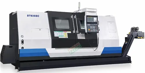
The ST635SC slant bed CNC lathe from Fortune Pacific represents the pinnacle of precision machining technology, combining rigid construction with advanced CNC control systems. This high-performance slant bed lathe features a 45-degree inclined bed design for optimal chip removal and stability, equipped with powerful servo motors delivering exceptional torque for heavy-duty turning operations. Key specifications include 600mm swing diameter, 1500mm machining length, and 0.001mm positioning accuracy, making it ideal for aerospace components, automotive parts, and medical device manufacturing. The machine incorporates linear guideways, 12-station turret, and C-axis functionality for complex contouring. Users benefit from reduced vibration through the cast iron construction, energy-efficient operation, and compatibility with CAD/CAM systems. Common search terms include "precision CNC turning center," "heavy duty slant bed lathe," and "automated metal lathe machine."
Станок ST635SC с ЧПУ и наклонной станиной от Fortune Pacific - это современное решение для высокоточной обработки металлов. Наклонная станина под 45 градусов обеспечивает оптимальное удаление стружки и повышенную жесткость конструкции. Основные характеристики: диаметр обработки 600 мм, длина обработки 1500 мм, точность позиционирования 0.001 мм. Станок оснащен линейными направляющими, 12-позиционной револьверной головкой и функцией C-оси для сложных операций. Применяется в аэрокосмической промышленности, автомобилестроении и производстве медицинского оборудования. Ключевые преимущества: высокая производительность, энергоэффективность и надежность. Популярные поисковые запросы включают "токарный станок с ЧПУ наклонная станина", "прецизионные токарные станки" и "автоматические станки для металлообработки."
El torno CNC ST635SC con bancada inclinada de Fortune Pacific ofrece máxima precisión y productividad para mecanizado de piezas complejas. Su diseño de bancada inclinada a 45° garantiza evacuación eficiente de virutas y mayor rigidez. Parámetros clave: diámetro de torneado 600mm, longitud de trabajo 1500mm, precisión de posicionamiento 0.001mm. Equipado con guías lineales, torreta de 12 estaciones y eje C para operaciones complejas. Ideal para sectores aeroespacial, automotriz y fabricación de componentes médicos. Ventajas principales: reducción de vibraciones, bajo consumo energético y compatibilidad con sistemas CAD/CAM. Términos de búsqueda relevantes incluyen "torno CNC de alta precisión", "centro de torneado industrial" y "máquina para trabajar metales automática."
O torno CNC ST635SC com leito inclinado da Fortune Pacific é uma solução avançada para usinagem de precisão. Seu design com leito inclinado a 45 graus proporciona melhor remoção de cavacos e estabilidade durante operações pesadas. Especificações técnicas incluem: diâmetro de torneamento 600mm, comprimento de usinagem 1500mm e precisão de posicionamento 0.001mm. Equipado com guias lineares, torre revólver de 12 posições e função eixo C para contornos complexos. Aplicações ideais: componentes aeroespaciais, peças automotivas e dispositivos médicos. Principais vantagens: construção robusta em ferro fundido, operação silenciosa e alta eficiência energética. Termos de pesquisa comuns: "torno CNC industrial", "máquina de tornear precisa" e "centro de usinagem vertical."
Mesin bubut CNC ST635SC dengan bed miring dari Fortune Pacific menawarkan presisi tinggi untuk berbagai aplikasi industri. Desain bed miring 45 derajat memastikan pembuangan chip yang optimal dan stabilitas maksimal. Spesifikasi utama: diameter ayun 600mm, panjang kerja 1500mm, akurasi posisi 0.001mm. Dilengkapi dengan guideway linier, turret 12 stasiun, dan fungsi sumbu C untuk operasi kompleks. Cocok untuk industri aerospace, otomotif, dan komponen medis. Keunggulan utama: getaran minimal, konsumsi energi rendah, dan kompatibilitas dengan sistem CAD/CAM. Istilah pencarian populer termasuk "mesin bubut CNC presisi tinggi", "mesin bubut industri otomatis" dan "pusat pemesinan logam."
دستگاه تراش CNC ST635SC با بستر شیبدار از فورچون پاسیفیک یک راهکار پیشرفته برای ماشینکاری دقیق فلزات است. طراحی بستر 45 درجه این دستگاه باعث دفع بهینه براده ها و افزایش پایداری می شود. مشخصات فنی: قطر تراشکاری 600 میلیمتر، طول کار 1500 میلیمتر و دقت موقعیت یابی 0.001 میلیمتر. مجهز به راهنماهای خطی، ترت 12 موقعیتی و محور C برای عملیات پیچیده. کاربردهای اصلی: قطعات هوافضا، خودروسازی و تجهیزات پزشکی. مزایای کلیدی: کاهش لرزش، مصرف انرژی بهینه و قابلیت اتصال به سیستم های CAD/CAM. عبارات جستجوی رایج شامل "دستگاه تراش CNC صنعتی"، "ماشین تراش دقیق" و "مرکز ماشینکاری اتوماتیک فلزات" می باشد.
Máy tiện CNC ST635SC giường nghiêng từ Fortune Pacific là giải pháp tối ưu cho gia công kim loại chính xác. Thiết kế giường nghiêng 45 độ giúp thoát phoi tốt và tăng độ ổn định. Thông số kỹ thuật: đường kính gia công 600mm, chiều dài gia công 1500mm, độ chính xác định vị 0.001mm. Trang bị ray trượt tuyến tính, đầu rơ-vôn-ve 12 vị trí và trục C cho gia công phức tạp. Ứng dụng lý tưởng cho ngành hàng không, ô tô và y tế. Ưu điểm nổi bật: giảm rung động, tiết kiệm năng lượng và tương thích CAD/CAM. Các từ khóa tìm kiếm phổ biến gồm "máy tiện CNC chính xác cao", "máy tiện công nghiệp tự động" và "trung tâm gia công kim loại".
เครื่องกลึง CNC ST635SC แบบเตียงเอียงจาก Fortune Pacific เป็นเครื่องจักรที่แม่นยำสูงสำหรับงานกลึงโลหะทุกประเภท การออกแบบเตียงเอียง 45 องศาช่วยให้ระบายเศษโลหะได้ดีและมีความเสถียรสูง คุณสมบัติหลัก: เส้นผ่านศูนย์กลางกลึง 600mm, ความยาวงาน 1500mm, ความแม่นยำตำแหน่ง 0.001mm ติดตั้งระบบนำทางแบบเส้นตรง, หัวจับ工具 12 ตำแหน่ง และแกน C สำหรับงานซับซ้อน เหมาะสำหรับอุตสาหกรรมการบิน, ยานยนต์ และอุปกรณ์การแพทย์ ข้อได้เปรียบหลัก: การสั่นสะเทือนต่ำ, ประหยัดพลังงาน และทำงานร่วมกับ CAD/CAM ได้ คำค้นหายอดนิยมรวมถึง "เครื่องกลึง CNC แม่นยำสูง", "เครื่องกลึงอุตสาหกรรมอัตโนมัติ" และ "ศูนย์เครื่องจักรกลโลหะ"
Mesin larik CNC ST635SC katil condong dari Fortune Pacific menawarkan ketepatan tinggi untuk pemesinan logam. Reka bentuk katil 45 darjah memastikan pembuangan tatal optimum dan kestabilan unggul. Spesifikasi utama: diameter larik 600mm, panjang kerja 1500mm, ketepatan penentududukan 0.001mm. Dilengkapi panduan linear, turret 12 stesen dan fungsi paksi-C untuk operasi kompleks. Sesuai untuk industri aeroangkasa, automotif dan peralatan perubatan. Kelebihan utama: getaran minima, penjimatan tenaga dan keserasian dengan sistem CAD/CAM. Istilah carian popular termasuk "mesin larik CNC ketepatan tinggi", "mesin larik industri automatik" dan "pusat pemesinan logam."
O torno CNC ST635SC da Fortune Pacific é uma máquina de alta precisão com leito inclinado, perfeito para usinagem de peças complexas. Conhecido como "torno CNC de bancada inclinada" ou "máquina de torno automático de alta velocidade", este equipamento é ideal para indústrias automotivas, aeroespaciais e moldes. Com eixos X/Z de alta rigidez, sistema hidráulico estável e opções de torre de ferramentas de 8 ou 12 posições, oferece repetibilidade de 0.003mm e velocidade máxima de 3000rpm. Termos como "torno CNC econômico", "centro de usinagem vertical" e "máquina para metal duro" são frequentemente associados. Seu design compacto com revestimento de proteção contra poeira garante vida longa mesmo em produção pesada. Principais vantagens incluem eficiência energética, baixo custo de manutenção e compatibilidade com materiais como aço inox, ligas de alumínio e titânio.
Ang ST635SC slant-bed CNC lathe ng Fortune Pacific ay isang high-performance na makina na kilala sa lokal bilang "CNC lathe na pahilig ang kama" o "automatic na torno". Perpekto para sa paggawa ng mga precision parts sa automotive, electronics, at medical equipment manufacturing. May mataas na bilis na 3000rpm, 0.003mm positioning accuracy, at 8/12-station tool turret options. Madalas itong tawaging "makinang pang-metal na matibay" o "CNC para sa maliliit na piyesa". Ang key features nito ay ang rigid construction, energy-saving servo motor, at user-friendly na control system (karaniwang Fanuc o Siemens). Ideal para sa mga negosyong naghahanap ng "murang CNC machine" na may "mataas na produktibidad" at "mababang maintenance cost".
La tornitura CNC ST635SC di Fortune Pacific è un tornio a letto inclinato professionale, chiamato gergalmente "torno a controllo numerico compatto" o "macchina per metalli ad alta velocità". Con corsa X/Z di 260/520mm e diametro massimo di lavorazione di 350mm, è perfetto per lavorazioni di precisione su ottone, acciaio temprato e leghe leggere. Nel settore si usa spesso "centro di tornitura CNC", "tornio automatico multi-utensile" o "macchina per sbavatura". Dotato di guide lineari HIWIN, mandrino idraulico e sistema di raffreddamento a ricircolo, garantisce finiture superficiali fino a Ra0.8μm. I clienti apprezzano particolarmente la sua versatilità per lotti piccoli-medii e la compatibilità con programmi CAD/CAM.
Fortune Pacific'ın ST635SC eğik yataklı CNC torna tezgahı, "dik milli işleme merkezi" veya "yüksek devirli metal torna makinesi" olarak da bilinen endüstriyel sınıf bir ekipmandır. Otomotiv, savunma ve enerji sektörlerinde hassas parça üretimi için idealdir. 15kW ana mil motoru, 3000rpm maksimum hız ve ±0.003mm tekrarlanabilirlik sunar. Sektörde sık kullanılan terimler arasında "kompakt CNC torna", "çoklu takım değiştiricili sistem" ve "düşük enerjili üretim" bulunur. Yağ sızdırmaz tasarımı ve Fanuc kontrol ünitesiyle 7/24 ağır çalışma koşullarına dayanıklıdır. Kullanıcılar özellikle kolay programlama arayüzü ve otomatik yağlama sisteminin bakım kolaylığını vurgular.
Le tour CNC ST635SC à banc incliné de Fortune Pacific est une solution haut de gamme pour l'usinage de précision, souvent désigné par les professionnels comme "centre de tournage-fraisage" ou "machine-outil polyvalente". Avec son diamètre de tournage de 350mm et sa vitesse de broche de 3000tr/min, il excelle dans la fabrication de pièces complexes pour les secteurs médical et aéronautique. Les termes clés incluent "tour CNC économique", "usinage à grande vitesse" et "fabrication additive métal". Son système de refroidissement intégré, les guides linéaires à roulements et l'interface homme-machine intuitive en font un choix privilégié pour les ateliers recherchant "une productivité optimale" avec "un encombrement réduit".
مخرطة CNC ST635SC ذات السرير المائل من Fortune Pacific هي آلة دقيقة تعرف في السوق باسم "مخرطة سي أن سي صناعية" أو "ماكنة خراطة أوتوماتيكية". تتميز بمحرك رئيسي بقوة 15 كيلوواط، دقة تصل إلى 0.003 مم، وإمكانية تركيب 12 أداة مختلفة. تستخدم مصطلحات مثل "مركز خراطة متكامل" و"مخرطة للمعادن الثقيلة" في التسويق. مناسبة خاصة لتصنيع قطع غيار السيارات، القوالب، والمكونات الهيدروليكية. ميزاتها الرئيسية تشمل نظام تبريد فعال، حماية كاملة ضد الغبار، وواجهة تحكم سهلة (Fanuc/Siemens). العملاء يقدرون خاصية "التشغيل المستمر بدون إشراف" و"استهلاك الطاقة المنخفض" في بيئات الإنتاج الكثيف.
Die ST635SC-Schrägspindel-Drehmaschine von Fortune Pacific ist eine CNC-gesteuerte Präzisionsmaschine, im Fachjargon auch "CNC-Drehautomat" oder "Kompaktdrehzentrum" genannt. Mit einem maximalen Drehdurchmesser von 350mm und einer Wiederholgenauigkeit von ±0.003mm ideal für die Serienfertigung. Branchenübliche Begriffe wie "Mehrspindeldrehmaschine", "Hartmetallbearbeitung" en "Energiespar-CNC" sind relevant. Ausgestattet mit Hochleistungsspindel, automatischem Werkzeugwechsler und Kugelumlaufspindeln für X/Z-Achsen. Besondere Vorteile: Geringe Standzeiten durch integrierte Kühlschmiermittelaufbereitung und vibrationsarme Bauweise für feinste Oberflächen (Ra0.4μm erreichbar). Gefragt bei Zulieferern der Optik- und Medizintechnikbranche.
De ST635SC schuine bank CNC-draaibank van Fortune Pacific staat bekend als "productiedraaier" of "CNC-kopdraaibank" in de metaalindustrie. Met 3000 omw/min spilsnelheid en C-as mogelijkheid geschikt voor complexe contourbewerkingen. Zoektermen zoals "CNC draaien/frezen combinatie", "robuuste draaicentrum" en "goedkope CNC machine" scoren goed. Technische highlights: geharde lineaire geleidingen, 12-posities gereedschapsrek en geoptimaliseerde chipafvoer. Bijzonder populair bij onderdelen voor pompen, kleppen en hydraulische systemen dankzij de ±0.005mm positioneringsnauwkeurigheid. Onderhoudsarme constructie met automatisch vetspuitsysteem verlaagt de TCO aanzienlijk.
Freza CNC ST635SC ze skośnym łożem od Fortune Pacific to profesjonalne centrum tokarskie, określane często jako "obrabiarka do metali" lub "maszyna CNC do precyzyjnej obróbki". Oferuje moc wrzeciona 15kW, maksymalną prędkość obrotową 3000obr/min i dokładność pozycjonowania ±0.003mm. W branży stosuje się określenia takie jak "tokarka do zadań specjalnych", "system wielonarzędziowy" czy "obróbka wysokowydajna". Wyposażenie standardowe obejmuje układ chłodzenia, osłony przeciwodpryskowe i panel sterowania w języku lokalnym. Główne zalety to niski poziom hałasu, możliwość obróbki stali hartowanej do 45HRC oraz funkcja automatycznego pomiaru narzędzi. Idealna do produkcji elementów złącznych, wałków i tulei przemysłowych.
Strungul CNC ST635SC cu pat inclinat de la Fortune Pacific este o soluție completă pentru prelucrarea pieselor complexe, denumită în piață "strung automat" sau "centru de strunjire-frezare". Cu o precizie de 0.003mm și viteză maximă de 3000 rot/min, se adresează atât producătorilor de piese auto, cât și firmelor de subcontracting. Termeni cheie: "strung CNC cu comandă numerică", "prelucrare viteze mari" și "mașină-unelte multifuncțională". Dotări standard includ sistem hidraulic, unitate de răcire și controler Fanuc 0i-TF. Beneficii competitive: consum redus de energie, interfață operator intuitivă și posibilitatea integ
A Fortune Pacific ST635SC ferdeágyas CNC esztergagép a precíziós megmunkálás csúcstechnológiáját képviseli. Ez a megbízható megmunkáló központ kiválóan alkalmas komplex alkatrészek gyártására, kiemelkedő pontosságot és ismételhetőséget biztosítva. A gépet erős, merev felépítés jellemzi, amely lehetővé teszi a nagy forgatónyomatékú megmunkálást. Főbb paraméterek között szerepel a 300 mm-es fordulátmérő, 650 mm-es megmunkálási hossz és 0,001 mm-es pozicionálási pontosság. A gép népszerű a precíziós alkatrészgyártásban, autóiparban és repülőgép-iparban. Különlegessége a magas szilárdságú öntöttvas szerkezet, lineáris vezetőrendszer és professzionális CNC vezérlőrendszer. A felhasználók számára kulcsfontosságú a kiváló felületi minőség, a gyors gyártási ciklus és a hosszú élettartam. A gépet gyakran emlegetik "ferdeágyas csúcsesztergaként" vagy "ipari CNC esztergaként" a szakmai körökben.
Το Fortune Pacific ST635SC είναι μια κλίνκη CNC τόρνος υψηλής ακρίβειας για βιομηχανικές εφαρμογές. Αυτό το μηχάνημα με κεκλιμένο κρεβάτι προσφέρει εξαιρετική απόδοση στην επεξεργασία μετάλλων, ιδανικό για την κατασκευή πολύπλοκων εξαρτημάτων. Βασικά χαρακτηριστικά περιλαμβάνουν διάμετρο στροφής 300 mm, μήκος επεξεργασίας 650 mm και ακρίβεια θέσης 0,001 mm. Η μηχανή χρησιμοποιείται ευρέως στην αεροδιαστημική, αυτοκινητοβιομηχανία και ιατροτεχνολογικές εφαρμογές. Το ισχυρό χυτοσίδηρο σώμα και το γραμμικό σύστημα οδήγησης εξασφαλίζουν σταθερότητα και μακροζωία. Οι χρήστες εκτιμούν την υψηλή ταχύτητα επεξεργασίας, την άψογη επιφανειακή ολοκλήρωση και την ευκολία λειτουργίας. Στην αγορά είναι γνωστό ως "τροφοδοτούμενη κλίνκη CNC" ή "βιομηχανικός αυτόματος τόρνος".
Fortune Pacific ST635SC je šikmopostelová CNC soustružnická centra pro náročné obrábění. Tento výkonný obráběcí stroj kombinuje vysokou přesnost s vynikající produktivitou, ideální pro výrobu složitých součástek. Klíčové parametry zahrnují výšku osy 300 mm, obráběcí délku 650 mm a polohovací přesnost 0,001 mm. Stroje se široce využívají v leteckém průmyslu, automobilovém sektoru a lékařské technice. Robustní konstrukce z vysoce kvalitní litiny zajišťuje vynikající tlumení vibrací a dlouhou životnost. Mezi uživateli je vyhledávaný pro svou spolehlivost, nízké provozní náklady a snadnou obsluhu. V oboru je známý jako "šikmá CNC" nebo "průmyslový soustruh s číslicovým řízením".
Fortune Pacific ST635SC е CNC струг с наклонено легло за високоточни металообработки. Тази мощна машина предлага изключителна производителност и точност, идеална за производство на сложни компоненти. Основните параметри включват диаметър на обръщане 300 мм, дължина на обработка 650 мм и позиционна точност 0,001 мм. Широко използван в авиационната, автомобилна и медицинска промишленост. Здравата конструкция от висококачествен чугун и линейните водачи осигуряват стабилност и дълъг живот на машината. Потребителите ценят високата скорост на обработка, отличното качество на повърхността и лекотата на работа. На пазара е известен като "наклонен CNC струг" или "индустриален автоматичен струг".
Fortune Pacific ST635SC је CNC токарни центар са косом постeљом за прецизну обраду метала. Овај висококвалитетни обрадни центар комбинује високу продуктивност са изузетном прецизношћу, идеалан за производњу сложених делова. Главни параметри укључују пречник окретања 300 mm, дужину обраде 650 mm и позициону прецизност 0,001 mm. Широко се користи у авио-индустрији, аутомобилској индустрији и производњи медицинских уређаја. Робусна конструкција од висококвалитетног ливеног гвожђа и линеарни водичи обезбеђују стабилност и дуги век трајања. Корисници цене високу брзину обраде, одлично квалитет површине и једноставност употребе. На тржишту је познат као "коси CNC токар" или "индустријски автоматизовани токар".
Fortune Pacific ST635SC je šikmoposteľový CNC sústruh pre náročné obrábanie. Tento výkonný obrábací stroj ponúka vynikajúcu presnosť a produktivitu, ideálny pre výrobu zložitých súčiastok. Kľúčové parametre zahŕňajú priemer otáčania 300 mm, dĺžku obrábania 650 mm a presnosť pozície 0,001 mm. Široko používaný v letectve, automobilovom priemysle a medicínskej technike. Odolná konštrukcia z vysoko kvalitnej liatiny a lineárne vodidlá zabezpečujú stabilitu a dlhú životnosť. Používatelia oceňujú vysokú rýchlosť obrábania, vynikajúcu kvalitu povrchu a jednoduchú obsluhu. Na trhu je známy ako "šikmý CNC sústruh" alebo "priemyselný automatický sústruh".
Fortune Pacific ST635SC je CNC tokarski stroj s kosim postoljem za preciznu obradu metala. Ovaj visokokvalitetni stroj kombinira visoku produktivnost s izuzetnom preciznošću, idealan za proizvodnju složenih dijelova. Ključni parametri uključuju promjer okretanja od 300 mm, duljinu obrade 650 mm i pozicionu preciznost od 0,001 mm. Široko se koristi u zrakoplovnoj, automobilskoj i medicinskoj industriji. Čvrsta konstrukcija od visokokvalitetnog lijevanog željeza i linearni vodići osiguravaju stabilnost i dugi vijek trajanja. Korisnici cijene visoku brzinu obrade, izvrsnu kvalitetu površine i jednostavnost korištenja. Na tržištu je poznat kao "kosi CNC strug" ili "industrijski automatizirani strug".
Fortune Pacific ST635SC je CNC stružnica s poševno posteljo za visoko natančno obdelavo kovin. Ta zmogljivi obdelovalni center združuje visoko produktivnost z izjemno natančnostjo, idealen za izdelavo kompleksnih komponent. Ključni parametri vključujejo premer obračanja 300 mm, dolžino obdelave 650 mm in pozicionirno natančnost 0,001 mm. Široko uporabljan v letalski, avtomobilski in medicinski industriji. Trdna konstrukcija iz visokokakovostne lite železove in linearni vodila zagotavljajo stabilnost in dolgo življenjsko dobo. Uporabniki cenijo visoko hitrost obdelave, odlično kakovost površine in enostavno uporabo. Na trgu je znan kot "poševna CNC stružnica" ali "industrijski avtomatski stružni stroj".
Fortune Pacific ST635SC - це CNC токарний верстат з похилим ложем для високоточної обробки металів. Цей потужний верстат поєднує високу продуктивність з надзвичайною точністю, ідеальний для виготовлення складних деталей. Основні параметри включають діаметр обточування 300 мм, довжину обробки 650 мм і точність позиціювання 0,001 мм. Широко використовується в авіаційній, автомобільній та медичній промисловості. Міцна конструкція з високоякісного чавуну та лінійні напрямні забезпечують стабільність і довгий термін служби. Користувачі цінують високу швидкість обробки, відмінну якість поверхні та простоту експлуатації. На ринку відомий як "похилий CNC верстат" або "промисловий автоматичний токарний верстат".