| Item | SL161H |
| Capability | |
| Max. swing over bed | Φ500mm(19.7’’) |
| Max. swing over saddle | Φ300mm(11.8’’) |
| Max. turning diameter | Φ210mm(8.2’’) |
| Max. machining length | 320mm(12.6’’) |
| Bar capacity | Φ44mm(1.7’’) |
| Spindle | |
| Spindle motor output power | 5.5/7.5kW |
| Spindle nose | A2-5 |
| Max. spindle speed | 6000rpm |
| Spindle bore diameter | Φ56mm(2.2’’) |
| Chuck size | 6” inch (Hydraulic hollow) |
| X/Z axis travel | |
| X-axis travel | 180mm(7.1’’) |
| Z-axis travel | 350mm(13.8’’) |
| Rapid traverse of X-axis | 30m/min(1181 IPM) |
| Rapid traverse of Z-axis | 30m/min(1181 IPM) |
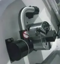
| Turret | |
| Number of tool | 8 |
| Turing tool size | 20x20mm |
| Max. boring tool diameter | Φ32mm |
| Tailstock (optional) | |
| Hydraulic tailstock center | MT4(live center) |
| Quill diameter | 65mm |
| Quill travel | 80mm |
| Accuracy | |
| Positioning accuracy (X/Z-axis) | 0.006/0.006mm |
| Repeatability (X/Z-axis) | 0.004/0.004mm |
| Others | |
| Power capacity | 15 kVA |
| Machine dimension (L x W x H) | 1850x2250x1550mm |
| Net weight | 2600kg |
| Item 01 | Descriptions | |
| 01.01 | FANUC Oi TF | |
| 01.02 | 6000rpm belt drive spindle (FANUC servo motor) | |
| 01.03 | 8 position hydraulic turret (refer to follow turret information) | |
| 01.04 | 6’’ hollow hydraulic chuck with 1 set soft jaw | |
| 01.05 | Solid hydraulic cylinder | |
| 01.06 | Hydraulic system | |
| 01.07 | Air conditioner of electrical cabinet | |
| 01.08 | Auto chip conveyer & chip chart | |
| 01.09 | Auto oil lubrication system | |
| 01.10 | Tri-color light | |
| 01.11 | Air gun | |
| 01.12 | Door lock switch | |
| 01.13 | Lighting lamp | |
| 01.14 | Full enclosure splash guard | |
| 01.15 | Telescopic covers |
| Item 02 | Descriptions | Note |
| 02.01 | SIEMENS 828D 240 | |
| 02.02 | Shop turn | |
| 02.03 | FANUC 0I TF 1 with β MOTOR | |
| 02.04 | FANUC 0I TF 1 with α MOTOR | |
| 02.05 | Manual guide 0I | |
| 02.06 | Manual guide I | for FANUC TF1 |
| 02.07 | DATA SERVE 2GB | for FANUC TF1 |
| 02.08 | 10.4” touch screen of FANUC controller | |
| 02.09 | 15” screen of FANUC controller | Only for FANUC 1 controller |
| 02.10 | 15” touch screen of FANUC controller | Only for FANUC 1 controller |
| 02.11 | 15” touch screen of SIEMENS controller | |
| 02.12 | Tool setter RENISHAW without parts catcher | Manual plug type |
| 02.13 | Tool setter RENISHAW without parts catcher | Auto swing type |
| 02.14 | Auto parts catcher without tool setter and tail stock | Chain belt type |
| 02.15 | Auto parts catcher without tool setter | Swing type |
| 02.16 | M30 auto power off | |
| 02.17 | Scraping chip conveyor for aluminums cutting | |
| 02.18 | Magnetic chip conveyor | |
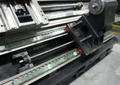
| 02.19 | THK linear way and ball screw | |
| 02.20 | Oil mister collector | |
| 02.21 | Auto-door (pneumatic control) | |
| 02.22 | 2 year FANUC warranty | |
| 02.23 | 2 year Siemens warranty | |
| 02.24 | CE standard | |
| 02.25 | 380V 50HZ/415V 50 HZ /220V 60 HZ | |
| 02.26 | Transformer | |
| 02.27 | Voltage stabilizer | |
| 02.28 | Grease lubrication instead of oil | |
| 02.29 | Bar feeder interface | |
| 02.30 | Auto bar feeder 26mm diameter, 3000mm length | |
| 02.31 | Auto bar feeder 65mm diameter, 1500mm length, DH65L | |
| 02.32 | Auto bar feeder 65mm diameter, 1250mm length, DH65 | |
| 02.33 | Hydraulic tailstock | |
| 02.34 | Servo tail stock | Programmable, ball screw and linear way |
| 02.35 | Live center of tail stock | |
| 02.36 | 8 position hydraulic turret, 20X20 | LioShing, working range change |
| 02.37 | 10 position hydraulic turret, 20X20 | LioShing, Long delivery time, working range change |
| 02.38 | 12 position hydraulic turret, 20X20 | LioShing, working range change |
| 02.39 | 8 position VDI-20 servo turret | LioShing, working range change |
| 02.40 | 6” hollow cylinder | |
| 02.41 | 8” solid chuck, 5000rpm | |
| 02.42 | 8” solid cylinder, 5000rpm | |
| 02.43 | 8” hollow chuck, 5000rpm | |
| 02.44 | 8” hollow cylinder, 5000rpm | |
| 02.45 | Hydraulic collet chuck DIN6343 | |
| 02.46 | Collet | |
| 02.47 | Soft jaw of 6” chuck | |
| 02.48 | Hard jaw of 6” chuck | |
| 02.49 | Soft jaw of 8” chuck | |
| 02.50 | Hard jaw of 8” chuck | |
| 02.51 | Manual 6” chuck | Change hydraulic chuck to manual chuck |
| 02.52 | A2-6 spindle bore 61mm, bar capacity 51mm, 5000rpm | |
| 02.53 | U drilling tool holder with coolant through 1.5bar/10 bar | Instead of the boring tool holder |
| 02.54 | Boring tool holder | |
| 02.55 | Boring tool holder sleeve (16, 20, 25) | |
| 02.56 | End face turning tool holder | |
| 02.57 | End face turning tool holder installation block | |
| 02.58 | Proximity switch (for chuck or tail stock) | |
| 02.59 | Coolant tank coolant level sensor | |
| 02.60 | Remove chip conveyer | |
| 02.61 | CNC controller book manuals | |
| 02.62 | Right side chip conveyer | Change backside to right side |
| 02.63 | Water gun | |
| 02.64 | MPG | |
| 02.65 | High pressure coolant 1MPa through turret | |
| 02.66 | High pressure coolant 2MPa through turret | |
| 02.67 | 7.5/11kw spindle motor β | |
| 02.68 | Roller linear guide way X/Z axis | |
| 02.69 | Two stage hydraulic pressure valve |
| ● Standard○ Optional X N/A | ||||||
| Specification | 0I-TF Plus | |||||
| Type 1 | Type 5 | |||||
| 1 | Controlled axis | Controlled axes | 4 | 4 | ||
| 2 | Axis control by PMC | ● | ● | |||
| 3 | Torque control | ● | ● | |||
| 4 | Inch/metric conversion | ● | ● | |||
| 5 | Stored limit check before move | ● | ● | |||
| 6 | Unexpected disturbance torque detection function | ● | ● | |||
| 7 | Position switch | ● | ● | |||
| 8 | Operation | DNC operation with memory card | ● | ● | ||
| 9 | Handle interruption | ● | ● | |||
| 10 | Manual handle retrace | ○ | ○ | |||
| 11 | Interpolation functions | Nano interpolation | ● | ● | ||
| 12 | Linear interpolation | ● | ● | |||
| 13 | Circular interpolation | ● | ● | |||
| 14 | Helical interpolation | ○ | X | |||
| 15 | Thread cutting, synchronous cutting | ● | ● | |||
| 16 | Thread cutting retract | ● | ● | |||
| 17 | Continuous threading | ● | ● | |||
| 18 | High-speed skip | Input signal is 8 points. | ● | ● | ||
| 19 | 2nd reference position return | G30 | ● | ● | ||
| 20 | Feed function | AI contour control I | ○ | ○ | ||
| 21 | AI contour control II | ○ | X | |||
| 22 | Rapid traverse block overlap | ● | ● | |||
| 23 | Program input | Optional block skip | 9 pieces | ● | ○ | |
| 24 | Absolute/incremental programming | Combined use in the same block | ● | ● | ||
| 25 | Diameter/Radius programming | ● | ● | |||
| 26 | Automatic coordinate system setting | ● | ● | |||
| 27 | Workpiece coordinate system | G52 - G59 | ● | ● | ||
| 28 | Chamfering/Corner R | ● | ● | |||
| 29 | Custom macro | ● | ● | |||
| 30 | Addition of custom macro common variables | #100 - #199, #500 - #999 | ● | ● | ||
| 31 | Interruption type custom macro | ● | ○ | |||
| 32 | Canned cycle | ● | ● | |||
| 33 | Multiple repetitive cycles | ● | ● | |||
| 34 | Multiple repetitive cycles II | Pocket profile | ● | ● | ||
| 35 | Canned cycle for drilling | ● | ● | |||
| 36 | Coordinate system shift | ● | ● | |||
| 37 | Direct input of coordinate system shift | ● | ● | |||
| 38 | Pattern data input | ● | ○ | |||
| 39 | Operation Guidance Function |
Manual Guide i | ○ | X | ||
| 40 | Manual Guide 0i | ○ | ○ | |||
| 41 | Auxiliary/ Spindle speed function | Constant surface speed control | ● | ● | ||
| 42 | Rigid tap | ● | ● | |||
| 43 | Arbitrary speed threading | ○ | ○ | |||
| 44 | Tool offset pairs | 128-pairs | ● | ● | ||
| 45 | Tool offset pairs | 200-pairs | ○ | X | ||
| 46 | Tool radius/Tool nose radius compensation | ● | ● | |||
| 47 | Tool geometry/wear compensation | ● | ● | |||
| 48 | Automatic tool offset | ● | ○ | |||
| 49 | Direct input of offset value measured B | ● | ○ | |||
| 50 | Tool life management | ● | ● | |||
| 51 | Accuracy compensation function | Backlash compensation for each rapid traverse and cutting feed | ● | ● | ||
| 52 | Stored pitch error compensation total value input | ○ | ○ | |||
| 53 | Editing operation | (Specify total of part program storage size of each path.) Number of registerable programs |
2Mbyte | ● | ● | |
| expansion 1 : Max. 1000 programs | ● | ● | ||||
| 54 | Playback | ● | ● | |||
| 55 | Data input/ output | Fast data server | ○ | X | ||
| 56 | External data input | ● | ● | |||
| 57 | Memory card input/output | ● | ● | |||
| 58 | USB memory input/output | ● | ● | |||
| 59 | Automatic data backup | ● | ● | |||
| 60 | Interface function | Embedded Ethernet | ● | ● | ||
| 61 | Fast Ethernet | ○ | ○ | |||
| 62 | Others | Display unit | 10.4" color LCD | ● | ● | |
| 63 | Robot interface | Robot interface with PMC I/O module | ○ | ○ | ||
| 64 | Robot interface with PROFIBUS-DP/PROFINET-DP | ○ | ○ | |||
| ● Standard ○ Optional X N/A | ||||||
| No. | Item | Spec. | S828D | |||
| SW24x | SW26x | SW28x | ||||
| 1 | Controlled axis | Controlled axes | 2 axes | X,Z | X,Z | X,Z |
| 2 | Additional controlled axes | 5 | 6+2 | 10+2 | ||
| 3 | Least command increment | 0.001mm (0.0001 inch) | ● | ● | ● | |
| 4 | Least input increment | 0.001mm (0.0001 inch) | ● | ● | ● | |
| 5 | Travel to fixed stop with Force Control | ○ | ○ | ○ | ||
| 6 | Interpolation & Feed Function | Reference point return | G75 FP=1 | ● | ● | ● |
| 7 | 2nd reference point return | G75 FP=2 | ● | ● | ● | |
| 8 | Inverse time feedrate | G93 | ● | ● | ● | |
| 9 | Helical interpolation | ● | ● | ● | ||
| 10 | Polynomial interpolation | X | X | X | ||
| 11 | Spline interpolation (A, B and C splines) | ○ | ○ | ○ | ||
| 12 | Separate path feedrate for roundings and chamfers | ● | ● | ● | ||
| 13 | Acceleration with Jerk limitation | ● | ● | ● | ||
| 14 | Compressor for 3-axis machining COMPCAD | X | X | X | ||
| 15 | Temperature compensation | ● | ● | ● | ||
| 16 | Look Ahead, recorded part program blocks: | Turning | 1 | 1 | 1 | |
| 17 | ||||||
| 18 | Look Ahead, IPO blocks, buffered: | Turning | 1 | 1 | 1 | |
| 19 | ||||||
| 20 | Cartesian point-to-point (PTP) travel | ● | ● | ● | ||
| 21 | TRANSMIT/cylinder surface transformation | ○ | ○ | ○ | ||
| 22 | Spindle Function | Tapping with compensating chuck/rigid tapping | ● | ● | ● | |
| 23 | Tool Function | Tool radius compensations in plane | ● | ● | ● | |
| 24 | Number of tools/cutting edges in tool list | 128/256 | 256/512 | 768/1536 | ||
| 25 | Tool length compensation | ● | ● | ● | ||
| 26 | Operation with tool management | ○ | ○ | ○ | ||
| 27 | Tool list | ● | ● | ● | ||
| 28 | Replacement tools for tool management | ○ | ○ | ○ | ||
| 29 | Monitoring of tool life and workpiece count | ● | ● | ● | ||
| 30 | Manual measurement of tool offset | ● | ● | ● | ||
| 31 | Magazine list | ● | ● | ● | ||
| 32 | Programming & Editing Function | Number of levels for skip blocks 2 | ● | ● | ● | |
| 33 | Number of levels for skip blocks 10 | ○ | ○ | ○ | ||
| 34 | Program/workpiece management | On additional plug-in CF card | ● | ● | ● | |
| 35 | On USB storage medium (e.g. disk drive, USB stick) | ● | ● | ● | ||
| 36 | On network drive | ○ | ○ | ○ | ||
| 37 | Program editor | Programming support for cycles program(Program Guide) | ● | ● | ● | |
| 38 | CNC editor with editing functions: select, copy, delete | ● | ● | ● | ||
| 39 | Programming graphics/free contour input (contour calculator) | ● | ● | ● | ||
| 40 | ShopTurn Machining step programming | ○ | ○ | ○ | ||
| 41 | Technology cycles for drilling/milling | ● | ● | ● | ||
| 42 | Pocket milling free contour and islands stock removal cycle | ○ | ● | ● | ||
| 43 | Residual material detection | ○ | ○ | ○ | ||
| 44 | Access protection for cycles | ○ | ○ | ○ | ||
| 45 | Programming support can be extended, e.g. customer cycles | ● | ● | ● | ||
| 46 | 2D simulation | ● | ● | ● | ||
| 47 | 3D simulation, finished part | ○ | ○ | ○ | ||
| 48 | OTHERS FUNCTIONS (Operation, setting & Display, etc) |
Switchover: inch/metric | ● | ● | ● | |
| 49 | Manual measurement of zero/work offset | ● | ● | ● | ||
| 50 | Automatic tool/workpiece measurement | ● | ● | ● | ||
| 51 | Reference point approach, automatic/via CNC program | ● | ● | ● | ||
| 52 | Execution from USB or CF card interface on operator panel front | ● | ● | ● | ||
| 53 | Execution from network drive | ○ | ○ | ○ | ||
| 54 | 10.4" color display | ● | ● | ● | ||
| 55 | 15.0" color display | ○ | ○ | ○ | ||
| 56 | Alarms and messages | ● | ● | ● | ||
| 57 | Automatic measuring cycles | ○ | ○ | ○ | ||
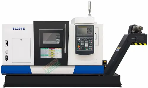
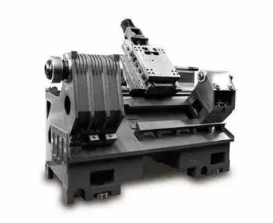
The SL161H Slant Bed CNC Lathe from Fortune Pacific is a high-precision turning machine designed for demanding machining applications. Known as a "CNC slant bed lathe" or "precision turning center," this industrial workhorse features a 30° inclined bed design that improves chip evacuation and rigidity. Equipped with a powerful spindle (up to 3000 rpm) and precision linear guides, it handles everything from aluminum alloys to tough steels. Manufacturers searching for "best slant bed CNC for small parts" or "high-accuracy chucking lathe" will appreciate its ±0.003mm repeatability and optional live tooling for milling operations. Common industry terms like "Swiss-type performance" and "production lathe" apply to this space-saving machine that's perfect for medical components, automotive fittings, and hydraulic parts production. Key search variations include "CNC lathe with C-axis," "multi-function turning center," and "compact CNC for precision turning."
Станок SL161H с ЧПУ от Fortune Pacific - это прецизионный токарный станок с наклонной станиной (30°), известный в отрасли как "станок с ЧПУ наклонной конструкции" или "производственный токарный центр". В русскоязычном сегменте часто ищут по запросам "токарный станок с ЧПУ для точной обработки" или "компактный станок для мелких деталей". Машина оснащена высокоточными линейными направляющими и шпинделем до 3000 об/мин, что делает её идеальной для обработки как алюминиевых сплавов, так и твёрдых сталей. В промышленности такой тип оборудования называют "прецизионный токарный станок" или "автомат продольного точения". Ключевые преимущества включают повторяемость ±0,003мм и возможность оснащения приводным инструментом (опция). Популярные поисковые фразы: "токарный станок с ЧПУ и осью C", "многофункциональный токарный центр", "наклонная станина для лучшего отвода стружки".
El torno CNC SL161H de Fortune Pacific es un equipo de torneado de alta precisión con bancada inclinada 30°, conocido en el mercado hispanohablante como "torno CNC de bancada inclinada" o "centro de torneado CNC". Buscado frecuentemente como "torno para piezas pequeñas" o "torno de alta precisión", este modelo destaca por su estructura rígida y sistema de guías lineales de precisión. En el sector industrial se le denomina "torno de producción" o "centro de torneado multifunción". Con un husillo de hasta 3000 rpm y repetitividad de ±0,003mm, es ideal para fabricar componentes médicos, piezas automotrices y accesorios hidráulicos. Términos SEO relevantes incluyen "torno CNC con eje C", "centro de torneado con herramientas motorizadas", y "torno compacto para trabajos de precisión". Los usuarios también buscan "mejor relación calidad-precio en tornos CNC" y "torno para producción en serie".
O torno CNC SL161H da Fortune Pacific é uma máquina de bancada inclinada (30°) de alta precisão, conhecida no mercado como "torno CNC de bancada inclinada" ou "centro de usinagem para torneamento". Frequentemente buscado como "torno para peças pequenas" ou "torno de alta produtividade", este equipamento possui guias lineares de precisão e alcança até 3000 rpm no fuso. Na indústria, é chamado de "torno de produção" ou "centro de torneado completo". Com repetibilidade de ±0,003mm e opção de ferramentas motorizadas, é perfeito para componentes médicos, autopeças e conexões hidráulicas. Termos importantes incluem "torno CNC com eixo C", "centro de torneado multifuncional", e "torno compacto de alta precisão". Os usuários também pesquisam por "melhor custo-benefício em tornos CNC" e "máquina para produção em série".
Mesin Bubut CNC SL161H dari Fortune Pacific adalah mesin bubut presisi dengan badan mesin miring 30°, dikenal di pasar sebagai "mesin bubut CNC slant bed" atau "pusat pembubutan CNC". Sering dicari dengan kata kunci "mesin bubut untuk part kecil" atau "mesin bubut presisi tinggi", model ini menonjolkan struktur kokoh dan sistem guideway linear presisi. Di industri, mesin ini disebut "mesin bubut produksi" atau "pusat pembubutan multi-fungsi". Dengan spindle hingga 3000 rpm dan akurasi ±0,003mm, ideal untuk komponen medis, part otomotif, dan fitting hidrolik. Istilah penting mencakup "mesin bubut CNC dengan sumbu C", "pusat pembubutan dengan alat potong bermotor", dan "mesin bubut kompak untuk pekerjaan presisi". Pengguna juga mencari "harga mesin bubut CNC terbaik" dan "mesin untuk produksi massal".
دستگاه تراش CNC مدل SL161H از فورچون پاسیفیک یک دستگاه تراش دقیق با بستر شیبدار (30 درجه) است که در بازار با نام "دستگاه تراش CNC بستر شیبدار" یا "مرکز تراشکاری CNC" شناخته می شود. این دستگاه که با عباراتی مانند "دستگاه تراش برای قطعات کوچک" یا "دستگاه تراش با دقت بالا" جستجو می شود، دارای ساختار مستحکم و سیستم راهنمای خطی دقیق است. در صنعت به آن "دستگاه تراش تولیدی" یا "مرکز تراشکاری چندمنظوره" می گویند. با اسپیندل تا 3000 دور در دقیقه و دقت تکرارپذیری ±0.003 میلیمتر، این دستگاه برای تولید قطعات پزشکی، خودرو و اتصالات هیدرولیک ایده آل است. عبارات کلیدی شامل "دستگاه تراش CNC با محور C"، "مرکز تراشکاری با ابزار موتوری" و "دستگاه تراش فشرده برای کارهای دقیق" می باشد. کاربران همچنین به دنبال "بهترین قیمت دستگاه تراش CNC" و "دستگاه برای تولید انبوه" هستند.
Máy tiện CNC SL161H từ Fortune Pacific là máy tiện chính xác cao với giường nghiêng 30°, được biết đến trên thị trường với tên gọi "máy tiện CNC giường nghiêng" hoặc "trung tâm tiện CNC". Thường được tìm kiếm với các từ khóa "máy tiện cho chi tiết nhỏ" hoặc "máy tiện độ chính xác cao", model này nổi bật với kết cấu cứng vững và hệ thống guideway tuyến tính chính xác. Trong ngành công nghiệp, máy được gọi là "máy tiện sản xuất" hoặc "trung tâm tiện đa chức năng". Với trục chính lên đến 3000 vòng/phút và độ lặp lại ±0.003mm, lý tưởng cho các chi tiết y tế, phụ tùng ô tô và khớp nối thủy lực. Các thuật ngữ quan trọng bao gồm "máy tiện CNC có trục C", "trung tâm tiện có dao động cơ", và "máy tiện nhỏ gọn cho gia công chính xác". Người dùng cũng tìm kiếm "máy tiện CNC giá tốt nhất" và "máy cho sản xuất hàng loạt".
เครื่องกลึง CNC SL161H จาก Fortune Pacific เป็นเครื่องกลึงความแม่นยำสูงแบบเตียงเอียง 30 องศา ที่รู้จักในตลาดในชื่อ "เครื่องกลึง CNC แบบเตียงเอียง" หรือ "ศูนย์กลึง CNC" มักถูกค้นหาด้วยคำสำคัญเช่น "เครื่องกลึงสำหรับชิ้นส่วนเล็ก" หรือ "เครื่องกลึงความแม่นยำสูง" รุ่นนี้โดดเด่นด้วยโครงสร้างที่แข็งแรงและระบบไกด์เวย์แบบเส้นตรงความแม่นยำสูง ในอุตสาหกรรมเรียกเครื่องนี้ว่า "เครื่องกลึงสำหรับการผลิต" หรือ "ศูนย์กลึงหลายหน้าที่" ด้วยความเร็วสปินเดิลสูงสุด 3000 รอบต่อนาที และความแม่นยำ ±0.003 มม. เหมาะสำหรับชิ้นส่วนทางการแพทย์ อะไหล่ยานยนต์ และข้อต่อไฮดรอลิก คำสำคัญรวมถึง "เครื่องกลึง CNC แกน C", "ศูนย์กลึงมีดตัดแบบมอเตอร์" และ "เครื่องกลึงขนาดกะทัดรัดสำหรับงานความแม่นยำสูง" ผู้ใช้ยังค้นหา "เครื่องกลึง CNC ราคาดีที่สุด" และ "เครื่องสำหรับการผลิตจำนวนมาก"
Mesin Larik CNC SL161H dari Fortune Pacific adalah mesin larik ketepatan tinggi dengan katil condong 30°, dikenali di pasaran sebagai "mesin larik CNC katil condong" atau "pusat larik CNC". Sering dicari dengan kata kunci "mesin larik untuk bahagian kecil" atau "mesin larik ketepatan tinggi", model ini menonjol dengan struktur kukuh dan sistem panduan linear tepat. Dalam industri, ia dipanggil "mesin larik pengeluaran" atau "pusat larik pelbagai fungsi". Dengan spindel sehingga 3000 rpm dan ketepatan ±0.003mm, sesuai untuk komponen perubatan, alat ganti kenderaan dan sambungan hidraulik. Istilah penting termasuk "mesin larik CNC dengan paksi C", "pusat larik dengan alat bermotor", dan "mesin larik padat untuk kerja tepat". Pengguna juga mencari "mesin larik CNC harga terbaik" dan "mesin untuk pengeluaran besar-besaran".
O torno CNC de leito inclinado SL161H da Fortune Pacific é a escolha profissional para usinagem de alta precisão. Conhecido no mercado brasileiro como "torno CNC pesado" ou "torno de bancada inclinada", esta máquina oferece rigidez excepcional e capacidade de corte poderosa. Os parâmetros técnicos incluem diâmetro de virada de 410mm e velocidade do fuso de 4500rpm, atendendo às demandas de oficinas mecânicas e linhas de produção industrial. A estrutura de leito inclinado de 45 graus, chamada localmente de "design escorregador", melhora a remoção de cavacos e estabilidade. Aplicações típicas incluem manufatura de eixos automotivos, componentes hidráulicos e peças de transmissão. Compradores procuram por "torno CNC com melhor custo-benefício" ou "máquina para usinagem de metais duros" frequentemente destacam nossa garantia estendida e sistema de controle Fanuc confiável.
Ang SL161H Slant Bed CNC Lathe ay isang high-performance na makina para sa precision machining, kilala sa industriya bilang "CNC lathe para sa heavy-duty na trabaho". Ang disenyo nitong may 45-degree na slant bed, tinatawag ding "angled CNC", ay nagbibigay ng superior na chip removal at rigidity. Mga teknikal na specs: 410mm turning diameter, 4500rpm spindle speed, at Fanuc control system. Ginagamit ito sa paggawa ng mga auto parts, hydraulic components, at precision shafts. Ang mga user ay naghahanap ng mga termino tulad ng "mataas na bilis na CNC lathe" o "makina para sa metal machining". Ang aming makina ay may features tulad ng high-accuracy ball screws, rigid tool post, at user-friendly interface. Kilala rin ito bilang "CNC lathe na pang-malupit na trabaho" sa mga lokal na workshop.
Il tornio CNC a letto inclinato SL161H di Fortune Pacific rappresenta l'eccellenza nella lavorazione di precisione. Chiamato comunemente "torno pesante CNC" o "torno a bancata inclinata", questa macchina unisce potenza e precisione con un diametro di tornitura di 410mm e velocità del mandrino fino a 4500rpm. La struttura a letto inclinato 45°, detta "a slitta inclinata", garantisce massima stabilità e smaltimento trucioli ottimale. Ideale per produzione di componenti automobilistici, alberi di trasmissione e parti idrauliche. I clienti cercano spesso "torno CNC ad alta produttività" o "macchina per lavorazioni pesanti". Dotato di controlli Fanuc, guide lineari ad alta precisione e cambio utensile rapido, è la scelta perfetta per officine meccaniche e reparti produzione.
Fortune Pacific SL161H Eğik Yataklı CNC Torna, yüksek hassasiyetli metal işleme için profesyonel çözümdür. Sektörde "ağır iş CNC torna" veya "eğimli yataklı torna" olarak bilinen bu makine, 410mm işleme çapı ve 4500rpm mil hızı sunar. 45 derecelik "eğik yatak" tasarımı, talaş boşaltmayı kolaylaştırır ve sert kesme işlemlerinde stabilite sağlar. Otomotiv parçaları, hidrolik komponentler ve dişli üretimi için idealdir. Kullanıcılar genellikle "yüksek verimli CNC torna" veya "sert metaller için torna tezgahı" gibi aramalar yapar. Fanuc kontrol sistemi, rijit takım tutucu ve yüksek hassasiyetli kızaklar ile öne çıkan bu makine, "endüstriyel üretim için vazgeçilmez ekipman" olarak tanımlanır.
Le tour CNC à banc incliné SL161H de Fortune Pacific est la référence pour l'usinage de précision. Appelé couramment "tour CNC lourd" ou "tour à banc incliné", cette machine offre un diamètre de tournage de 410mm et une vitesse de broche de 4500tr/min. La structure à banc incliné de 45°, appelée "design à glissières inclinées", améliore l'évacuation des copeaux et la stabilité. Applications typiques: fabrication de pièces automobiles, composants hydrauliques et arbres de transmission. Les acheteurs recherchent souvent des termes comme "tour CNC haut de gamme" ou "machine pour métaux durs". Équipé d'un système de contrôle Fanuc, de vis à billes de précision et d'un changeur d'outils rapide, ce tour est idéal pour les ateliers mécaniques exigeants.
مخرطة CNC ذات السرير المائل SL161H من Fortune Pacific هي الحل الأمثل للأعمال الدقيقة. تعرف في السوق باسم "مخرطة CNC ثقيلة" أو "مخرطة سرير مائل"، هذه الآلة توفر دقة فائقة بقطر دوران 410مم وسرعة مغزل تصل إلى 4500 دورة/دقيقة. تصميم السرير المائل بزاوية 45 درجة، المعروف محليًا باسم "سرير منزلق"، يحسن إزالة الرايش والثبات. التطبيقات تشمل تصنيع قطع السيارات، المكونات الهيدروليكية وأعمدة النقل. يبحث العملاء عن مصطلحات مثل "مخرطة CNC عالية الجودة" أو "آلة تشغيل المعادن الدقيقة". مزودة بنظام تحكم Fanuc، مسامير كرات عالية الدقة وحامل أدوات متين، هذه المخرطة مثالية للمصانع والورش المتخصصة.
Die SL161H Schrägbett-Drehmaschine von Fortune Pacific ist die Premium-Lösung für präzise Metallbearbeitung. In der Branche bekannt als "CNC-Drehmaschine für schwere Arbeiten" oder "Schrägbettmaschine", bietet diese Maschine 410mm Drehdurchmesser und 4500 U/min Spindeldrehzahl. Das 45-Grad-"Schrägbett-Design" verbessert die Spanabfuhr und Stabilität bei harten Bearbeitungen. Ideal für Automobilteile, Hydraulikkomponenten und Präzisionswellen. Kunden suchen oft nach "hochpräziser CNC-Drehmaschine" oder "Drehmaschine für harte Metalle". Ausgestattet mit Fanuc-Steuerung, hochpräzisen Kugelumlaufspindeln und stabilem Werkzeugträger ist diese Maschine perfekt für anspruchsvolle Industrieeinsätze. Lokal wird sie auch als "Schwerlast-Drehmaschine" oder "Industrie-CNC mit langer Lebensdauer" bezeichnet.
De SL161H schuine bank CNC draaibank van Fortune Pacific is een topprecisie machine voor metaalbewerking. In de sector bekend als "zware CNC draaibank" of "schuine bank machine", biedt deze draaibank een draaidiameter van 410mm en een spilsnelheid tot 4500tpm. Het 45 graden "schuine bank ontwerp", lokaal soms "glijbed-machine" genoemd, verbetert de spanafvoer en stabiliteit. Toepassingen omvatten auto-onderdelen, hydraulische componenten en asproductie. Kopers zoeken vaak op termen zoals "hoogproductieve CNC draaibank" lub "maszyna do obróbki metali". Wyposażony w system sterowania Fanuc, precyzyjne śruby kulowe i sztywną głowicę narzędziową, ten tokarek CNC jest idealny do profesjonalnych zastosowań przemysłowych.
Strungul CNC cu pat înclinat SL161H de la Fortune Pacific este soluția premium pentru prelucrarea precisă a metalelor. Cunoscut în industrie ca "strung CNC greu" sau "strung cu pat înclinat", această mașină oferă un diametru de strunjire de 410mm și viteză axului principal de 4500 rpm. Designul cu pat înclinat la 45°, numit local "pat glisant", îmbunătățește evacuarea așchiilor și stabilitatea. Aplicații tipice: componente auto, piese hidraulice și arbori de transmisie. Cumpărătorii caută adesea termeni ca "strung CNC de înaltă precizie" sau "mașină pentru metale dure". Echipat cu sistem de control Fanuc, șuruburi cu bile de precizie și post rigid pentru scule, acest strung CNC este ideal atât pentru ateliere, cât și pentru linii de producție industriale.
A Fortune Pacific SL161H ferdeágyas CNC esztergagép a precíziós megmunkálás csúcstechnológiáját képviseli. Ez a megbízható megmunkáló központ kiválóan alkalmas komplex alkatrészek gyártására, kiemelkedő pontosságot és ismételhetőséget biztosítva. A gép főbb paraméterei között szerepel a 160 mm-es forgatási átmérő, 1-1,5 m-es megmunkálási hosszúság és 0,001 mm-es pozicionálási pontosság. A robusztus konstrukció hidraulikus tokmányzóval, lineáris vezetőkkel és magas nyomatékú szervomotorokkal rendelkezik. Az ipari felhasználók különösen értékelik a Fanuc vagy Siemens vezérlőrendszerek lehetőségét, valamint az automata szerszámváltó integrált változatát. A gép kiválóan használható orvosi eszközök, repülőgép-alkatrészek és precíziós műszerek gyártásához, ahol a mikronos pontosság elengedhetetlen.
Το Fortune Pacific SL161H CNC πλαγιοκρεμάς τόρνος είναι μια επανάσταση στην ακριβή μηχανοκατεργασία. Αυτό το βιομηχανικό μηχάνημα με κλίση 45 μοιρών προσφέρει αξιοπιστία κλάσης προτύπου με ταχύτητες περιστροφής έως 4000 rpm και ακρίβεια θέσης 0,001 mm. Οι κύριες εφαρμογές του περιλαμβάνουν την κατασκευή αυτοκινητοβιομηχανίας, αεροδιαστημικών εξαρτημάτων και ιατρομηχανικών συσκευών. Το μηχάνημα διαθέτει υδραυλικό τσάκι, γραμμικούς οδηγούς με μπαλικές βίδες και προηγμένο σύστημα αυτόματης αλλαγής εργαλείων. Οι τεχνολογίες "High Speed Machining" και "Rigid Tapping" καθιστούν αυτόν τον τόρνο ιδανικό για σύνθετες εργασίες. Οι χρήστες εκτιμούν ιδιαίτερα την ενσωματωμένη λύση ψύξης, τον ψηφιακό πίνακα ελέγχου και τη δυνατότητα ολοκλήρωσης με ρομποτικά συστήματα.
Fortune Pacific SL161H šikmé lože CNC soustruh představuje špičku v obráběcích technologiích. Tento výkonný obráběcí stroj s úhlem náklonu 45° nabízí vynikající stabilitu a přesnost díky lineárním vodítkům a vysokokapacitním ložiskům. Mezi klíčové parametry patří obráběcí průměr 160 mm, posuvová rychlost až 15 m/min a opakovatelnost 0,005 mm. Stroj je vybaven moderním řídicím systémem (volitelně Fanuc nebo Siemens), automatickou výměnou nástrojů a integrovaným chladicím systémem. V automobilovém průmyslu a leteckém inženýrství se tento soustruh osvědčil pro výrobu přesných komponentů. Uživatelé oceňují zejména "plug-and-play" funkce, nízké vibrace a možnost připojení k průmyslovému IoT prostředí.
Фортун Пасифик SL161H CNC наклонен струг е иновативно решение за високоточни металообработващи операции. Този 45-градусов струг с цифрово управление предлага впечатляваща производителност с максимална скорост на въртене 4000 об/мин и резолюция 0,001 мм. Ключовите характеристики включват тежка чугунена конструкция, хидравлична патронка и опция за автоматична смяна на инструменти. Машината се използва предимно в автомобилната, аерокосмическата и медицинската промишленост за производство на сложни компоненти. Специалните функции като "Термокомпенсация" и "Интелигентно управление на износването на инструменти" гарантират дългосрочна точност. Потребителите оценяват лесното програмиране, ниските експлоатационни разходи и възможността за интеграция с ERP системи.
Fortune Pacific SL161H CNC токарни стан са косом креветом представља врхунско решење за прецизну обраду метала. Овај индустријски цнц токарни са нагибним леђима од 45 степени поседује Fanuc или Siemens контролни систем, са резолуцијом од 0,001 mm и брзином обртаја до 4000 rpm. Кључне предности укључују интегрисани систем за хлађење, аутоматску промену алата и могућност "Dry Machining" операција. Стан је идеалан за производњу компоненти у аутомобилској индустрији, ваздухопловству и медицинској техници. Посебне функције као што су "C-Axis Contouring" и "Live Tooling" омогућавају израду сложених делова у једном оперативном циклусу. Корисници истичу изузетну крутост конструкције, ниске вибрације и дуги век трајања машине.
Fortune Pacific SL161H CNC sústruh so šikmou posteľou je špičkové riešenie pre presnú obrábku kovov. Tento výkonný obrábací stroj s uhlom sklonu 45° ponúka maximálnu flexibilitu vďaka voliteľnému Fanuc alebo Siemens riadiacemu systému. Medzi hlavné parametre patří obrábací priemer 160 mm, rýchlosť posuvu až 15 m/min a presnosť pozíciovania 0,001 mm. Stroj je vybavený automatickou výmenou nástrojov, lineárnymi vodidlami a integrovaným chladiacim systémom. V automobilovom priemysle a leteckom inžinierstve sa tento sústruh osvedčil pri výrobe presných komponentov. Používatelia oceňujú najmä možnosť "Tandem Operation", nízke vibrácie a jednoduchú integráciu do priemyselnej automatizácie.
Fortune Pacific SL161H CNC tokarski stroj s kosim ležištem predstavlja vrhunsko rješenje za preciznu obradu metala. Ovaj industrijski CNC stroj s nagibom od 45 stupnjeva ima Fanuc ili Siemens upravljački sustav, s rezolucijom od 0,001 mm i brzinom vrtnje do 4000 o/min. Ključne prednosti uključuju integrirani sustav hlađenja, automatsku izmjenu alata i mogućnost "Dry Machining" operacija. Strojevi su idealni za proizvodnju komponenti u automobilskoj industriji, zrakoplovstvu i medicinskoj tehnici. Posebne funkcije kao što su "C-Axis Contouring" i "Live Tooling" omogućuju izradu složenih dijelova u jednom operativnom ciklusu. Korisnici ističu izuzetnu krutost konstrukcije, niske vibracije i dugi vijek trajanja stroja.
Fortune Pacific SL161H CNC stružnica s poševno postavljeno osnovo je vrhunska rešitev za natančno obdelavo kovin. Ta industrijski CNC stroj z naklonom 45 stopinj ponuja izjemno natančnost s pozicionirno natančnostjo 0,001 mm in hitrostjo vrtenja do 4000 vrt/min. Ključne lastnosti vključujejo hidravlično glavo, linearna vodila in možnost avtomatskega menjanja orodja. Stroji se uporabljajo predvsem v avtomobilski, letalski in medicinski industriji za izdelavo kompleksnih komponent. Posebne funkcije kot so "Visokohitrostno rezkanje" in "Ciklično rezkanje" omogočajo učinkovito obdelavo materialov. Uporabniki posebej cenijo enostavno programiranje, nizko porabo energije in možnost integracije v pametne tovarne.
Верстат з ЧПК SL161H з похилим ложем від Fortune Pacific - це високотехнологічне рішення для прецизійної обробки металів. Цей токарний верстат з кутом нахилу 45° оснащений сучасною системою керування (Fanuc або Siemens) та забезпечує точність позиціювання до 0,001 мм. Ключові переваги включають гідравлічний патрон, лінійні напрямні та опцію автоматичної зміни інструментів. Верстат ідеально підходить для виробництва точних компонентів у авіаційній, автомобільній та медичній промисловості. Спеціальні функції, такі як "C-вісьова обробка" та "Обробка з обертовим інструментом", дозволяють виконувати складні операції за одну установку деталі. Користувачі відзначають високу жорсткість конструкції, низький рівень вібрацій та можливість інтеграції в системи автоматизованого виробництва.