| Model | Unit | WGM500 |
| CNC system | NUM1050 | |
| Workpiece outer diameter | mm | Φ100-500 (3.9-20”) |
| Workpiece module: single start | mm | 2-8 |
| No. of teeth: single start | 12-256 | |
| Max teeth width (spur gear) | mm | 200 (7.9”) |
| Max helix angle | degree | ±30 |
| Distance between headstock center and tailstock center | mm | 250-550 (9.8-22”) |
| Max travel of work rest | mm | 220 (8.7”) |
| Rapid traverse of work rest | mm/min | 1000 |
| Working speed of work rest | mm/min | 8-300 |
| Distance between grinding wheel axis and work rest center | mm | 210-550 (8.3-22”) |
| Grinding wheel speed: grinding / dressing | rpm | 1100-1650 / 40 |
| Grinding wheel size | mm | Φ400x203x100 (16x8x3.9”) |
| Radial automatic feed of wheelhead per stroke | mm | 0.01-0.5 |
| Max travel of wheel head | mm | 315 (12”) |
| Max travel of dresser in wheel spindle direction: axial / radial | mm | 165 / 85 (6.5 / 3.4”) |
| Total tangential travel of column | mm | 90 (3.5”) |
| Taper hole of spindle | MT-4 | |
| Taper hole of tailstock center | MT-4 | |
| Total motor power | kW | 35 |
| Overall dimension (L x W x H) | mm | 2910x1860x2400 |
| Net weight | kg | 11000 |
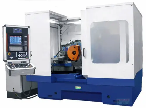
WGM500 CNC Worm Wheel Grinding Machine delivers unparalleled precision for demanding gear manufacturing. This advanced CNC machine utilizes continuous generating grinding with vitrified CBN or aluminum oxide wheels to achieve micron-level accuracy (≤1.5 μm) on worm wheels and gears. Featuring a robust cast iron structure, Siemens 840D sl CNC control, and multi-axis synchronized movement, it ensures exceptional surface finish and profile consistency. Key applications include high-precision reducers, steering systems, aerospace actuators, and heavy machinery transmissions. Its automated wheel dressing, in-process gauging (optional), and rigid design guarantee high productivity, minimal setup time, and long-term reliability for mass production of critical components. Operators value its user-friendly interface, energy efficiency, and low maintenance requirements. Search for precision worm gear grinding, CNC gear grinder solutions, high-accuracy gear finishing machine, or industrial worm wheel production equipment.
Станок WGM500 для шлифования червячных колес с ЧПУ — это решение для прецизионного производства зубчатых передач. Используя метод непрерывного обката шлифовальными кругами из керамики CBN или электрокорунда, станок обеспечивает микронную точность (≤1,5 мкм) обработки червячных колес и шестерен. Жесткая чугунная конструкция, система ЧПУ Siemens 840D sl и синхронизированное многокоординатное движение гарантируют идеальное качество поверхности и профиля. Применяется в производстве высокоточных редукторов, рулевых механизмов, аэрокосмических приводов и тяжелых трансмиссий. Автоматическая правка круга, встроенный контроль (опция) и надежная конструкция обеспечивают высокую производительность, минимальное время переналадки и долговечность для крупносерийного выпуска ответственных деталей. Операторы ценят интуитивный интерфейс, энергоэффективность и низкие затраты на обслуживание. Ищите: прецизионное шлифование червячных колес, станки ЧПУ для шлифовки шестерен, высокоточное зубошлифовальное оборудование, промышленные решения для производства червячных пар, шлифовка зубьев червяка.
La máquina rectificadora CNC para ruedas de tornillo sinfín WGM500 ofrece precisión inigualable para la fabricación exigente de engranajes. Esta máquina CNC avanzada utiliza rectificado generativo continuo con muelas vitrificadas de CBN o óxido de aluminio para lograr precisión a nivel de micras (≤1,5 μm) en ruedas sinfín y engranajes. Con una robusta estructura de fundición, control CNC Siemens 840D sl y movimiento sincronizado multieje, garantiza un acabado superficial excepcional y consistencia del perfil. Sus aplicaciones clave incluyen reductores de alta precisión, sistemas de dirección, actuadores aeroespaciales y transmisiones para maquinaria pesada. El afilado automático de la muela, el control en proceso (opcional) y su diseño rígido aseguran alta productividad, mínimo tiempo de preparación y confiabilidad a largo plazo para producción en serie de componentes críticos. Los operadores valoran su interfaz amigable, eficiencia energética y bajos requerimientos de mantenimiento. Busque: rectificado preciso de engranajes sinfín, soluciones de rectificadora CNC para engranajes, máquina de acabado de engranajes de alta precisión, o equipo de producción industrial para ruedas sinfín.
A retificadora CNC para engrenagens de coroa sem-fim WGM500 oferece precisão incomparável para fabricação de engrenagens de alto desempenho. Esta máquina CNC avançada utiliza retificação geradora contínua com rebolos vitrificados de CBN ou óxido de alumínio para alcançar precisão micrométrica (≤1,5 μm) em coroas sem-fim e engrenagens. Com estrutura robusta em ferro fundido, controle CNC Siemens 840D sl e movimento sincronizado multi-eixo, garante acabamento superficial excepcional e consistência de perfil. Aplicações-chave incluem redutores de alta precisão, sistemas de direção, atuadores aeroespaciais e transmissões para máquinas pesadas. Seu rebolo com afiação automática, medição em processo (opcional) e projeto rígido proporcionam alta produtividade, tempo mínimo de setup e confiabilidade de longo prazo para produção em massa de componentes críticos. Operadores valorizam sua interface intuitiva, eficiência energética e baixa necessidade de manutenção. Procure por: retificação precisa de engrenagens sem-fim, soluções de retificadora CNC para engrenagens, máquina de acabamento de engrenagens de alta precisão, ou equipamento de produção industrial para coroas sem-fim.
Mesin Gerinda Roda Gigi Cacing CNC WGM500 memberikan presisi tak tertandingi untuk manufaktur gigi yang menuntut. Mesin CNC mutakhir ini menggunakan metode gerinda generasi kontinu dengan batu gerinda vitrified CBN atau aluminium oksida untuk mencapai akurasi tingkat mikron (≤1,5 μm) pada roda gigi cacing (worm wheel) dan berbagai gear. Dengan struktur besi cor yang kokoh, kontrol CNC Siemens 840D sl, dan gerakan multi-sumbu tersinkronisasi, mesin ini memastikan finishing permukaan luar biasa dan konsistensi profil. Aplikasi utamanya meliputi reducer presisi tinggi, sistem kemudi (steering), aktuator aerospace, dan transmisi mesin berat. Fitur dressing roda gerinda otomatis, pengukuran in-process (opsional), serta desain rigid menjamin produktivitas tinggi, waktu setup minimal, dan keandalan jangka panjang untuk produksi massal komponen kritis. Operator menghargai antarmuka yang user-friendly, efisiensi energi, dan kebutuhan perawatan rendah. Cari: gerinda presisi roda gigi cacing, solusi mesin gerinda gear CNC, mesin finishing gear akurasi tinggi, atau peralatan produksi worm wheel industri.
دستگاه سنگزنی چرخ دنده حلزونی (وُرم ویل) مدل WGM500 با کنترل CNC، دقتی بینظیر برای تولید چرخ دندههای حلزونی ارائه میدهد. این دستگاه پیشرفته CNC از روش سنگزنی ژنراتور پیوسته با سنگهای ویتریفاید CBN یا اکسید آلومینیوم استفاده میکند تا به دقتی در حد میکرون (≤۱.۵ میکرون) در سنگزنی چرخ دندههای حلزونی و انواع چرخ دنده دست یابد. با ساختار چدنی مستحکم، کنترلر CNC Siemens 840D sl، و حرکت هماهنگ چندمحوره، کیفیت سطح عالی و یکنواختی پروفیل را تضمین میکند. کاربردهای کلیدی شامل تولید ریدوسرهای دقیق، سیستمهای فرمان، محرکهای هوافضا و گیربکسهای ماشینآلات سنگین میشود. سیستم اصلاح (dressing) اتوماتیک سنگ، اندازهگیری در فرآیند (اختیاری) و طراحی صلب آن، بهرهوری بالا، زمان تنظیم حداقل و قابلیت اطمینان بلندمدت را برای تولید انبوه قطعات حیاتی تضمین میکند. اپراتورها رابط کاربری آسان، مصرف انرژی بهینه و نیاز به نگهداری کم را ارزشمند میدانند. جستجو کنید: سنگزنی دقیق چرخ دنده حلزونی، راهحلهای دستگاه سنگزنی چرخ دنده CNC، دستگاه پرداخت چرخ دنده با دقت بالا، یا تجهیزات تولید صنعتی چرخ دنده حلزونی.
Máy mài bánh răng trục vít CNC WGM500 đạt độ chính xác vượt trội cho sản xuất bánh răng yêu cầu cao. Máy CNC tiên tiến này sử dụng phương pháp mài bao hình liên tục với đá mài liền kết CBN hoặc nhôm oxit để đạt độ chính xác cấp micron (≤1.5 μm) trên bánh răng trục vít (worm wheel) và các loại bánh răng. Với kết cấu gang đúc vững chắc, hệ điều khiển CNC Siemens 840D sl và chuyển động đồng bộ đa trục, đảm bảo độ bóng bề mặt hoàn hảo và độ đồng đều biên dạng. Ứng dụng chính bao gồm bộ giảm tốc chính xác cao, hệ thống lái, cơ cấu chấp hành hàng không vũ trụ và hộp số máy móc hạng nặng. Tính năng tự động đá mài, đo lường trong quá trình (tùy chọn) cùng thiết kế cứng vững đảm bảo năng suất cao, thời gian thiết lập tối thiểu và độ tin cậy lâu dài cho sản xuất hàng loạt linh kiện quan trọng. Người vận hành đánh giá cao giao diện thân thiện, tiết kiệm năng lượng và nhu cầu bảo trì thấp. Tìm kiếm: máy mài bánh răng trục vít chính xác, giải pháp máy mài bánh răng CNC, máy gia công tinh bánh răng độ chính xác cao, hoặc thiết bị sản xuất bánh răng trục vít công nghiệp.
เครื่องกัดล้อเกียร์หนอน CNC รุ่น WGM500 ให้ความแม่นยำระดับไมครอน (≤1.5 μm) สำหรับงานผลิตเกียร์ที่ต้องใช้ความละเอียดสูง เครื่องซีเอ็นซีขั้นสูงนี้ใช้วิธีการกัดเจเนอเรทีฟแบบต่อเนื่องด้วยล้อกัด CBN หรืออลูมิเนียมออกไซด์แบบวิทริไฟด์ เพื่อสร้างล้อเกียร์หนอน (worm wheel) และเกียร์ประเภทต่าง ๆ ด้วยความแม่นยำสูง โครงสร้างเหล็กหล่อที่แข็งแกร่ง ระบบควบคุมซีเอ็นซี Siemens 840D sl และการเคลื่อนไหวแบบมัลติแอกซิสที่ประสานกันอย่างสมบูรณ์ ทำให้ได้ผิวงานคุณภาพสูงและโปรไฟล์ที่สม่ำเสมอ ใช้งานหลักในอุตสาหกรรมเช่น รีดิวเซอร์ความแม่นยำสูง ระบบพวงมาลัย แอคทูเอเตอร์สำหรับการบินและอวกาศ รวมถึงเกียร์ส่งกำลังเครื่องจักรหนัก ระบบปรับล้อตัดอัตโนมัติ การวัดในกระบวนการ (ออปชั่น) และการออกแบบที่มั่นคงแข็งแรง ทำให้ผลิตภาพสูง เวลาตั้งเครื่องน้อยสุด และความน่าเชื่อถือระยะยาวสำหรับการผลิตชิ้นส่วนสำคัญจำนวนมาก ผู้ปฏิบัติงานชื่นชอบอินเตอร์เฟซที่ใช้งานง่าย ประหยัดพลังงาน และต้องการการบำรุงรักษาน้อย ค้นหา: เครื่องกัดล้อเกียร์หนอนความแม่นยำสูง, เครื่องกัดเกียร์ซีเอ็นซี, เครื่องตกแต่งเกียร์ความละเอียดสูง, หรืออุปกรณ์ผลิตล้อเกียร์หนอนอุตสาหกรรม.
Mesin Pengisar Gear Cacing CNC WGM500 menawarkan ketepatan yang tiada tandingan untuk pembuatan gear berprestasi tinggi. Mesin CNC canggih ini menggunakan kaedah pengisaran penjanaan berterusan dengan roda pengisar bersadur CBN atau aluminium oksida untuk mencapai ketepatan peringkat mikron (≤1.5 μm) pada gear cacing (worm wheel) dan pelbagai jenis gear. Dengan struktur besi tuang yang kukuh, kawalan CNC Siemens 840D sl, dan pergerakan paksi berganda yang disegerakkan, ia memastikan kemasan permukaan yang unggul dan konsistensi profil. Aplikasi utama termasuk gear penurun (reducer) ketepatan tinggi, sistem stereng, penggerak aeroangkasa, dan penghantaran kuasa untuk jentera berat. Ciri pembentuk roda automatik, pengukuran dalam-proses (pilihan), dan reka bentuk tegar menjamin produktiviti tinggi, masa persediaan minima serta kebolehpercayaan jangka panjang untuk pengeluaran besar-besaran komponen kritikal. Operator menghargai antara muka mesra pengguna, kecekapan tenaga, dan keperluan penyelenggaraan yang rendah. Cari: pengisaran gear cacing tepat, penyelesaian mesin pengisar gear CNC, mesin kemasan gear ketepatan tinggi, atau peralatan pengeluaran worm wheel industri.
A WGM500 é uma retificadora CNC de última geração para engrenagens helicoidais (parafuso sem-fim e coroa), essencial para indústrias de alta precisão como aeronáutica, automotiva e energética. Esta máquina-ferramenta robusta, conhecida como "retífica para coroas" ou "equipamento de usinagem de engrenagens cônicas", utiliza tecnologia CNC avançada para garantir acabamento superficial excepcional (Ra ≤ 0.4 μm) e tolerâncias apertadíssimas (DIN 3). Seu eixo C rotativo contínuo e eixo B de alta precisão permitem usinagem complexa de perfis globoidais e helicoidais. Componentes críticos como o cabeçote de retificação com motorização direta, mesa giratória de alta rigidez e sistema hidráulico de alta resposta garantem repetibilidade e confiabilidade ("troca de ferramentas automática", "controle térmico inteligente"). Principais vantagens: eficiência elevada (redução drástica do ciclo), precisão absoluta (±0.003mm), baixa vibração e manutenção simplificada. Configurações incluem opcionais como medidor de engrenagens integrado, sistema de balanceamento automático de rebolos e interface avançada de programação "user-friendly". Ideal para fabricantes de redutores, caixas de câmbio e componentes críticos que exigem "durabilidade extrema" e "qualidade certificada".
Ang WGM500 ay isang cutting-edge na CNC worm wheel gear grinding machine, kilala rin bilang "CNC gear grinder" o "precision worm gear grinder," na espesyal para sa paggawa ng mga high-precision worm gear at wheel para sa mga industriya tulad ng aviation, automotive, at heavy machinery. Gumagamit ito ng advanced na CNC control para sa kamangha-manghang katumpakan (±0.003mm tolerance) at makinis na surface finish (Ra ≤ 0.4μm). Ang matibay na istruktura nito, kasama ang patuloy na umiikot na C-axis at high-rigidity na B-axis, ay nagbibigay-daan para sa kumplikadong profile grinding gaya ng globoid at helical gears. Pangunahing komponente: high-power grinding spindle, precision rotary table, at awtomatikong tool changer para sa walang patid na operasyon. Malinaw na benepisyo: napakataas na kahusayan (mabilis na cycle time), superyor na katumpakan para sa maayos na pag-engage ng gear, mahusay na pagiging maaasahan ("matibay na makina," "mababang maintenance"), at kakayahang umangkop para sa iba't ibang laki ng gear. May opsyon itong built-in gear measuring system at user-friendly programming interface. Perpekto para sa paggawa ng mga reducer, gearbox, at kritikal na bahagi na nangangailangan ng "matinding tibay" at "de-kalidad na output".
La WGM500 è una rettificatrice CNC all'avanguardia per ruote dentate elicoidali (vite senza fine e corona), indispensabile per settori ad alta precisione come aerospaziale, automotive ed energia. Questa macchina utensile robusta, chiamata anche "rettificatrice per corone" o "centro di lavoro per ingranaggi conici", utilizza tecnologia CNC avanzata per garantire una finitura superficiale eccezionale (Ra ≤ 0,4 μm) e tolleranze strettissime (DIN 3). Il suo asse C rotante continuo e l'asse B ad alta precisione consentono la lavorazione complessa di profili globoidi ed elicoidali. Componenti critici come la testa di rettifica con motorizzazione diretta, la tavola rotante ad alta rigidità e il sistema idraulico ad alta risposta assicurano ripetibilità e affidabilità ("cambio utensile automatico", "controllo termico intelligente"). Vantaggi principali: efficienza elevata (riduzione drastica del ciclo), precisione assoluta (±0,003mm), vibrazioni ridotte e manutenzione semplificata. Le configurazioni includono opzioni come misuratore d'ingranaggi integrato, sistema di bilanciamento automatico della mola e interfaccia di programmazione avanzata "user-friendly". Ideale per produttori di riduttori, scatole del cambio e componenti critici che richiedono "durata estrema" e "qualità certificata".
WGM500, son teknoloji CNC solucularıyla "solucan dişlisi taşlama" ve "konik dişli işleme merkezi" olarak bilinen, havacılık, otomotiv ve enerji gibi sektörler için hassas solucan dişlileri ve karşılık dişlileri üreten üst düzey bir taşlama makinesidir. Bu "yüksek rijitlikli dişli taşlama tezgahı", ±0.003mm hassasiyet ve Ra ≤ 0.4μm yüzey kalitesi sunar. Sürekli dönen C-ekseni ve yüksek sertlikteki B-ekseni ile globoid ve helisel dişli profillerinin karmaşık işlenmesini sağlar. Kritik bileşenler: yüksek güçlü taşlama mili, hassas döner tabla, otomatik takım değiştirici ("tam otomatik çalışma" için) ve termal stabilizasyon sistemi. Temel avantajlar: "yüksek verimlilik" (kısa çevrim süresi), "mükemmel dişli geçişi" için üstün hassasiyet, "düşük bakım maliyeti" ile güvenilirlik ve çeşitli dişli boyutları için esneklik. Opsiyonel entegre dişli ölçüm sistemi ve kolay kullanımlı programlama arayüzü mevcuttur. Redüktör, şanzıman ve "uzun ömürlü", "yüksek kaliteli" kritik parçalar üreten imalatçılar için idealdir.
La WGM500 est une rectifieuse CNC de pointe pour engrenages à vis sans fin et roues dentées, incontournable dans l'aérospatiale, l'automobile et l'énergie. Cette machine-outil robuste, appelée "rectifieuse pour roues dentées" ou "centre d'usinage d'engrenages coniques", utilise une commande CNC avancée pour une finition superficielle exceptionnelle (Ra ≤ 0,4 μm) et des tolérances très serrées (DIN 3). Son axe C rotatif continu et son axe B de haute précision permettent l'usinage complexe de profils globoïdes et hélicoïdaux. Composants critiques : broche de rectification haute puissance à motorisation directe, table tournante haute rigidité et système hydraulique haute réponse assurant répétabilité et fiabilité ("changement d'outil automatique", "compensation thermique intelligente"). Avantages majeurs : rendement élevé (temps de cycle réduit), précision absolue (±0,003mm), vibrations minimales et maintenance simplifiée. Configurations avec options : palpeur de mesure d'engrenages intégré, système d'équilibrage automatique de meule et interface de programmation conviviale. Idéale pour les fabricants de réducteurs, boîtes de vitesses et composants critiques exigeant "robustesse extrême" et "qualité certifiée".
آلة WGM500 هي ماكينة تجليخ تعمل بنظام التحكم الرقمي CNC عالية التطور لتصنيع تروس الدودة (اللولبية) والعجلات المسننة، وتعد ضرورية في صناعات الطيران والسيارات والطاقة. تعرف هذه الآلة الصناعية القوية باسم "ماكينة تجليخ التروس اللولبية" أو "مركز تشغيل التروس المخروطية"، وتستخدم تقنية CNC المتقدمة لضمان تشطيب سطحي استثنائي (Ra ≤ 0.4 ميكرومتر) ودقة تحملات فائقة (DIN 3). يوفر محور C الدوار المستمر ومحور B عالي الصلابة إمكانية تشغيل معقد للمقاطع الجلوبويدية واللولبية. تضمن المكونات الحرجة مثل رأس التجليخ عالي القدرة، الطاولة الدوارة شديدة الصلابة، ونظام التحكم الهيدروليكي سريع الاستجابة تكرارية وموثوقية عالية ("تبديل أدوات آلي"، "تحكم حراري ذكي"). المزايا الرئيسية: كفاءة عالية (تقليل وقت الدورة)، دقة مطلقة (±0.003 مم)، انخفاض الاهتزاز، وصيانة سهلة. تتضمن التكوينات خيارات مثل نظام قياس التروس المدمج، نظام اتزان العجلات التلقائي، وواجهة برمجة سهلة الاستخدام. مثالية لمصنعي المخفضات وصناديق التروس والمكونات الحرجة التي تتطلب "متانة قصوى" و"جودة معتمدة".
Die WGM500 ist eine hochmoderne CNC-Schneckenrad-Schleifmaschine, auch bekannt als "CNC-Zahnradschleifmaschine" oder "Präzisionsschneckenradschleifer", speziell für die Herstellung von hochpräzisen Schnecken und Schneckenrädern für Luftfahrt, Automobilbau und Schwerindustrie. Diese robuste Werkzeugmaschine ("Zahnradbearbeitungszentrum") nutzt fortschrittliche CNC-Steuerung für herausragende Genauigkeit (±0,003mm Toleranz) und Oberflächengüte (Ra ≤ 0,4μm). Die stabile Bauweise mit stetig drehender C-Achse und hochsteifer B-Achse ermöglicht komplexes Profilschleifen von Globoid- und Schraubzahnrädern. Schlüsselkomponenten: Hochleistungs-Schleifspindel, präzise Rundtisch, automatischer Werkzeugwechsler für unterbrechungsfreien Betrieb ("Rund-um-die-Uhr-Produktion") und Thermo-Kompensationssystem. Klare Vorteile: Hohe Effizienz (schnelle Zykluszeiten), überlegene Präzision für ruhigen Zahneingriff, hohe Zuverlässigkeit ("wartungsarm", "robuste Konstruktion") und Flexibilität für verschiedene Zahnradgrößen. Optional mit integriertem Zahnradmesssystem und benutzerfreundlicher Programmierschnittstelle. Ideal für Hersteller von Getrieben, Reduzierstufen und kritischen Komponenten, die "lange Lebensdauer" und "hochwertige Ausführung" benötigen.
De WGM500 is een geavanceerde CNC-wormwielslijpmachine, ook wel bekend als "CNC-tandwielslijpmachine" of "precisie wormwielslijper", speciaal ontworpen voor het vervaardigen van hoogwaardige wormwielen voor sectoren zoals luchtvaart, auto-industrie en zware mechanica. Deze robuuste "versnellingsbewerkingsmachine" maakt gebruik van geavanceerde CNC-besturing voor uitzonderlijke nauwkeurigheid (±0.003mm tolerantie) en oppervlakteafwerking (Ra ≤ 0.4μm). De stabiele constructie met continue roterende C-as en stijve B-as maakt complex profielslijpen mogelijk, zoals globoïde en spiraalvormige tandwielen. Belangrijke componenten: hoogvermogen slijpspoel, precisie draaitafel, automatisch gereedschapswisselsysteem voor ononderbroken productie ("stipte levering") en thermisch stabilisatiesysteem. Duidelijke voordelen: hoge efficiëntie (snelle cyclustijden), superieure precisie voor soepele tandwieloverbrenging, betrouwbaarheid ("onderhoudsarm", "degelijk gebouwd") en flexibiliteit voor diverse tandwielmaten. Optioneel met ingebouwd tandwielmeetsysteem en gebruiksvriendelijke programmeerinterface. Ideaal voor fabrikanten van reductiekasten, versnellingsbakken en kritieke onderdelen die "lange levensduur" en "topkwaliteit" eisen.
WGM500 to zaawansowana, sterowana numerycznie (CNC) szlifierka do kół zębatych ślimakowych, niezbędna w branżach wymagających najwyższej precyzji, takich jak lotnictwo, motoryzacja i energetyka. Ta solidna obrabiarka, znana również jako "szlifierka do kół stożkowych" lub "centrum obróbki kół zębatych", wykorzystuje zaawansowaną technologię CNC do uzyskania doskonałej gładkości powierzchni (Ra ≤ 0,4 μm) i wąskich tolerancji (DIN 3). Ciągle obracająca się oś C i sztywna oś B umożliwiają kompleksową obróbkę profili globoidalnych i śrubowych. Kluczowe komponenty: szlifierski wrzeciono z napędem bezpośrednim, wysoko sztywny stół obrotowy oraz system hydrauliczny gwarantują powtarzalność i niezawodność ("automatyczna zmiana narzędzi", "inteligentna kompensacja termiczna"). Główne zalety: wysoka wydajność (skrócony czas cyklu), absolutna precyzja (±0,003mm), minimalne wibracje i uproszczona konserwacja. Konfiguracje obejmują opcje, takie jak zintegrowany system pomiaru kół zębatych, automatyczny system równoważenia ściernic oraz zaawansowany, przyjazny interfejs programowania. Idealna dla producentów przekładni, skrzyń biegów i elementów krytycznych wymagających "najwyższej trwałości" i "potwierdzonej jakości".
WGM500 este o mașină de rectificat dinți pentru roți melcate CNC de ultimă oră, esențială în industrii de precizie ridicată precum aerospațial, auto și energie. Această mașină-unealtă robustă, cunoscută și ca "rectificatoare pentru roți dințate conice" sau "centru de prelucrare a angrenajelor", utilizează tehnologie CNC avansată pentru a garanta o finisare superficială excepțională (Ra ≤ 0,4 μm) și toleranțe strânse (DIN 3). Axa C rotativă continuă și axa B de înaltă rigiditate permit prelucrarea complexă a profilelor globoidale și elicoidale. Componentele critice: capul de rectificat cu acționare directă, masa rotativă de înaltă rigiditate și sistemul hidraulic de răspuns rapid asigură repetabilitate și fiabilitate ("schimbător automat de scule", "compensare termică inteligentă"). Beneficii principale: eficiență ridicată (reducere drastică a timpului de ciclu), precizie absolută (±0,003mm), vibrații reduse și întreținere simplificată. Configurațiile includ opțiuni precum sistem integrat de măsurare a angrenajelor, sistem automat de echilibrare a pietrelor abrazive și interfață avansată de programare "ușor de utilizat". Ideală pentru producătorii de reductoare, cutii de viteze și componente critice care necesită "durabilitate extremă" și "calitate certificată".
A futócsiga-fogaskerekek precíziós megmunkálására tervezett WGM500 CNC-es marógépen kiemelt hangsúlyt kapott a pontosság (1µm) és a megbízhatóság. A gépet Siemens vagy Fanuc CNC rendszer vezérli, és kiválóan alkalmas ipari sebességváltók, irányváltó mechanizmusok, emelőberendezések egyedi vagy sorozatgyártásához. Fő komponensei közé tartozik a merev váz, a nagy pontosságú orsóegység, az automatikus szerszámcsere (ATC), valamint a beépített mérési rendszer in-process ellenőrzésre. A géppel jelentősen növelhető a termelékenység, miközben garantált a hosszú élettartam és az alacsony karbantartási igény.
Το WGM500 είναι μια αυτόματος CNC μηχανή λείανσης σκωληκοειδών τροχών και γραναζιών, σχεδιασμένη για ακραία ακρίβεια (έως 1μm). Λειτουργεί με σύστημα Siemens/Fanuc CNC και είναι ιδανική για την παραγωγή σκωληκοειδών γραναζιών σε κιβώτια ταχυτήτων, βιομηχανικούς ανυψωτήρες και εφαρμογές αυτοματισμού. Βασικά χαρακτηριστικά: αυτόματη αλλαγή εργαλείων (ATC), ενσωματωμένο σύστημα μέτρησης για in-process έλεγχο, άκαμπτο πλαίσιο και υψηλής απόδοσης άξονας. Διασφαλίζει εξαιρετική επιφανειακή ομαλότητα, αυξημένη διάρκεια ζωής εξαρτημάτων και βέλτιστη σταθερότητα παραγωγής σε μαζική ή μοναδική κατασκευή.
WGM500 je špičkový CNC bruska na kuželová a šneková kola, optimalizovaná pro extrémní přesnost broušení (až 1μm) a vysokou opakovatelnost. Díky řídicímu systému Siemens/Fanuc CNC a automatické výměně nástrojů (ATC) je ideální pro sériovou i kusovou výrobu převodovek, průmyslových reduktorů a pohonných systémů. Hlavní výhody: robustní konstrukce, integrovaný měřicí systém pro kontrolu během procesu, minimální nároky na údržbu a vysoká energetická účinnost. Zajišťuje výrazné prodloužení životnosti komponentů a dokonalou kvalitu ozubení.
WGM500 е високоточна (до 1μm) CNC шлифовъчна машина за червячни колела, създадена за масово и единично производство на прецизни предавки. Оборудвана със системы Siemens/Fanuc CNC, автоматична смяна на инструменти (ATC) и вградена измерителна система за in-process контрол. Ключови приложения: промишлени скоростни кутии, подемни системи, автомобилни предавки. Предимства: изключителна издръжливост, намалени време за настройка, висока производителност и гарантирана надеждност при продължителна работа. Конструкцията включва твърда основа, високоскоростна шпиндела и автоматизирана смазочна система.
WGM500 је CNC машина за брушење завртњених точка и зупчаника, пројектована за постизање микро тачности (1μm) у производњи преносника, погонских система и индустријских редуктора. Опремљена системима Siemens/Fanuc CNC, аутоматском сменом алата (ATC) и уграђеним мерним системом за контролу током процеса. Предности: крута конструкција, минимални вибрације, висока поузданост и дуг век трајања. Идеална за серијску и прототипску производњу. Кључни параметри укључују велику брзину обртаја главног вретена, аутоматско позиционирање и напредну термокомпензацију за стабилност у свим радним условима.
WGM500 je presné CNC brúske na červové kolesá, určené pre dokonalú presnosť (až 1μm) a efektívnu výrobu prevodových sústáv. S ovládaním Siemens/Fanuc CNC, automatickou výmenou nástrojov (ATC) a integrovaným meracím systémom zabezpečuje maximálnu opakovateľnosť a kvalitu ozubenia. Hlavné aplikácie: priemyselné prevodovky, zdvíhacie zariadenia, strojárske komponenty. Výhody: nízké náklady na údržbu, vysoká produktivita, dlhá životnosť komponentov a robustná konštrukcia. Vybavenie zahŕňa vysokorýchlostné vreteno, systém tepelnej kompenzácie a automatické mazanie.
WGM500 je vrhunska CNC brusilica za pužne zupčanike, namijenjena visokopreciznoj obradi (do 1μm) u proizvodnji mjenjača, reduktora i industrijskih pogonskih sustava. Opremljena Siemens/Fanuc CNC upravljanjem, automatskom izmjenom alata (ATC) i ugrađenim mjernim sustavom za in-process kontrolu. Ključne prednosti: kruta konstrukcija, izvanredna površinska kvaliteta, produženi vijek trajanja zupčanika i smanjeno vrijeme postavljanja. Idealna za serijsku i prototipsku proizvodnju. Specifikacije uključuju veliku brzinu vretena, termalnu stabilnost i automatizirano podmazivanje.
WGM500 je napredni CNC brusilnik za črvična kolesa, zasnovan za mikro natančnost (1μm) in visoko zmogljivo brušenje zobnikov za menjalnike, dvigalne mehanizme in reduktorje. Opremljen s Siemens/Fanuc CNC krmilnikom, samodejno menjalnikom orodij (ATC) in vgrajenim merilnim sistemom za in-process nadzor. Prednosti: tog okvir, visoka hitrost vretena, zmanjšani vibraciji ter optimalna zanesljivost. Glavne komponente vključujejo visoko natančne vodilne tirnice, avtomatsko mazanje in napredno termokompensacijo. Omogoča dolgo življenjsko dobo komponent in izjemno gladkost površine.
WGM500 — це високоточний (до 1μm) CNC верстат для шліфування черв'ячних коліс, призначений для серійного виробництва прецизійних передач. Оснащений системами Siemens/Fanuc ЧПК, автоматичною зміною інструменту (ATC) та вбудованою вимірювальною системою для in-process контролю. Ключові переваги: жорстка конструкція станини, високошвидкісний шпіндель, мінімальні вібрації та зручне програмне забезпечення. Застосовується у виробництві редукторів, промислових лебідок та коробок передач. Забезпечує високу продуктивність, довговічність компонентів та стабільну якість при будь-яких навантаженнях.