| Model | Unit | WGM360 |
| Type | B | |
| CNC system | NUM1050 | |
| Workpiece outer diameter | mm | Φ20-360 (0.79-14”) |
| Workpiece module | mm | 1-6 |
| No. of teeth | 12-260 | |
| Max teeth width (spur gear) | mm | 190 (7.5”) |
| Max helix angle | degree | ±45 |
| Workpiece pressure angle | degree | 15-23 |
| Max workpiece weight (including fixture) | kg | 60 |
| Distance between headstock center and tailstock center | mm | 180-420 (7.1-17”) |
| Max travel of work rest | mm | 200 (7.9”) |
| Working speed of work rest | mm/min | 8-200 |
| Resolution of work rest | degree | 0.0001 |
| Distance between grinding wheel axis and work rest center | mm | 155-440 (6.1-17”) |
| Grinding wheel speed: grinding / dressing | rpm | 1000-1900 / 60 |
| Grinding wheel size | mm | Φ350x160x104 (14x6.3x4.1”) |
| Resolution of workpiece spindle | mm | 0.0001 |
| Max travel of wheel head | mm | 285 (11”) |
| Rapid travel of wheel head | mm | 40 (1.6”) |
| Resolution of wheel head | mm | 0.0001 |
| Max travel of dresser in wheel spindle direction: axial / radial | mm | 180 / 85 (7.1 / 3.4”) |
| Total tangential travel of column | mm | 90 (3.5”) |
| Resolution of column | mm | 0.0001 |
| Taper hole of spindle | MT-3 | |
| Taper hole of tailstock center | MT-3 | |
| Total motor power | kW | 30 |
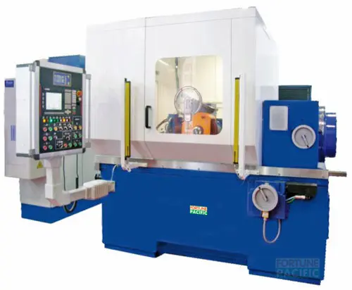
The WGM360-B CNC Worm Wheel Gear Grinding Machine delivers unmatched precision for high-volume worm gear production. This 5-axis CNC marvel utilizes continuous generation grinding with CBN or aluminum oxide wheels, achieving micron-level tolerances (±0.001mm repeatability) and superior surface finishes (Ra 0.2μm). Its rigid cast iron structure, precision ballscrews, and linear guides ensure stability during high-efficiency grinding cycles. Key components include the high-speed grinding spindle (up to 6000 RPM), automatic wheel dressing system, integrated coolant filtration, and user-friendly Siemens/Fanuc CNC with dedicated gear grinding software. Ideal for automotive steering systems, industrial gearboxes, and power transmission applications demanding quiet operation and long life. Reduce setup time, eliminate manual skill dependency, and boost throughput with this reliable, turnkey grinding solution. Explore automated loading options for lights-out production. High-accuracy CNC worm gear grinder, precision worm wheel grinding machine, industrial gear grinding equipment, CBN gear grinder, automated gear finishing system.
Вертикальный шлифовальный станок WGM360-B для червячных колес с ЧПУ — это решение для прецизионного чистового шлифования червячных передач. Машина использует метод обкатки с использованием кругов из CBN или электрокорунда, обеспечивая высочайшую точность (повторяемость ±0.001 мм) и идеальную шероховатость поверхности (Ra 0.2 мкм). Жесткая чугунная станина, прецизионные шарико-винтовые пары и линейные направляющие гарантируют устойчивость даже при интенсивной сухой или мокрой шлифовке. Оснащена высокоскоростным шпинделем (до 6000 об/мин), системой автоматической правки круга, ЧПУ Siemens/Fanuc со специализированным ПО для шлифования зубчатых колес и эффективной системой СОЖ. Незаменим для производства ответственных червячных пар в рулевых механизмах, редукторах, насосах и подъемном оборудовании, где критичны низкий шум и долговечность. Повысьте производительность, снизив время наладки. Станок червячный шлифовальный ЧПУ, прецизионное шлифование червячных колес, станок для шлифовки червяков, автоматическая обработка зубчатых передач, высокоточное зубошлифование, промышленное шлифовальное оборудование.
La rectificadora CNC para ruedas de tornillo sinfín WGM360-B ofrece máxima precisión en la producción en serie de engranajes sinfín. Esta máquina de 5 ejes emplea rectificado por generación continua con muelas de CBN ó óxido de aluminio, logrando tolerancias micrométricas (±0.001mm repetibilidad) y acabados superficiales excepcionales (Ra 0.2μm). Su robusta estructura de fundición, husillos a bolas de precisión y guías lineales aseguran estabilidad durante ciclos de rectificado de alta eficiencia. Componentes clave: husillo de rectificado de alta velocidad (hasta 6000 RPM), sistema automático de desbaste de muelas, filtración integrada de refrigerante y CNC Siemens/Fanuc fácil de usar con software dedicado para rectificado de engranajes. Ideal para sistemas de dirección automotriz, cajas de cambios industriales y transmisiones de potencia que exigen bajo ruido y larga vida útil. Reduzca tiempos de preparación, elimine dependencia de mano de obra calificada y aumente productividad con esta solución de rectificado confiable y llave en mano. Consulte opciones de carga automática. Máquina rectificadora CNC de ruedas helicoidales, rectificado de precisión de engranajes sinfín, rectificadora industrial de engranajes, rectificadora con muelas CBN, sistema automatizado de acabado de engranajes.
A retífica CNC para engrenagens de rosca sem-fim WGM360-B oferece precisão incomparável na produção em série de engrenagens sem-fim. Esta máquina de 5 eixos utiliza retificação por geração contínua com rebolos de CBN ou óxido de alumínio, alcançando tolerâncias de nível micrônico (±0.001mm repetibilidade) e acabamentos superficiais superiores (Ra 0.2μm). Sua estrutura rígida em ferro fundido, fusos de esferas de precisão e guias lineais garantem estabilidade durante ciclos de retificação de alta eficiência. Componentes principais: fuso de retificação de alta rotação (até 6000 RPM), sistema automático de dressagem de rebolo, filtragem integrada de refrigerante e CNC Siemens/Fanuc fácil de operar com software dedicado para retificação de engrenagens. Ideal para sistemas de direção automotiva, redutores industriais e transmissões de potência que demandam baixo ruído e longa vida útil. Reduza tempo de setup, elimine dependência de mão de obra especializada e impulsione a produtividade com esta solução de retificação confiável e "chave na mão". Máquina de retificar engrenagens sem-fim CNC, retificação de precisão de rodas de coroa, equipamento industrial de retificação de engrenagens, retificadora com rebolo CBN, sistema automatizado de acabamento de engrenagens.
Mesin Gerinda Roda Gigi Cacing CNC WGM360-B memberikan presisi tak tertandingi untuk produksi massal roda gigi cacing (worm wheel). Mesin 5-sumbu CNC ini menggunakan metode gerinda generasi berkelanjutan dengan roda gerinda CBN atau aluminium oksida, mencapai toleransi tingkat mikron (±0.001mm repetabilitas) dan permukaan akhir superior (Ra 0.2μm). Struktur besi cor kokoh, ballscrew presisi, dan linear guide menjamin stabilitas selama siklus gerinda berkecepatan tinggi. Komponen utama meliputi spindle gerinda ber-RPM tinggi (hingga 6000 RPM), sistem dress roda otomatis, filtrasi coolant terintegrasi, dan CNC Siemens/Fanuc ramah pengguna dengan software khusus gerinda roda gigi. Ideal untuk sistem kemudi otomotif, gearbox industri, dan aplikasi transmisi daya yang membutuhkan operasi senyap dan umur panjang. Kurangi waktu setup, hilangkan ketergantungan keahlian manual, dan tingkatkan hasil produksi dengan solusi gerinda andal siap pakai ini. Mesin gerinda CNC worm gear presisi tinggi, mesin gerinda roda cacing industri, alat gerinda gigi otomatis, mesin dengan batu gerinda CBN, sistem finishing gear berpresisi.
دستگاه سنگ زنی چرخ دنده و حلزونی (کرم و چرخ دنده) CNC مدل WGM360-B با دقت بی نظیر برای تولید انبوه چرخ دنده های حلزونی طراحی شده است. این دستگاه 5 محوره CNC از روش سنگ زنی ژنراتوری پیوسته با چرخ سنگ CBN یا اکسید آلومینیوم استفاده می کند و به تلرانس های میکرونی (±0.001mm تکرارپذیری) و پرداخت سطح عالی (Ra 0.2μm) دست می یابد. ساختار چدنی صلب، بالاسروهای دقیق و راهنماهای خطی، پایداری را در طی چرخه های سنگ زنی پربازده تضمین می کند. اجزای کلیدی شامل: اسپیندل سنگ زنی پرسرعت (تا 6000 دور در دقیقه)، سیستم اتوماتیک اصلاح چرخ سنگ (Dressing)، فیلتراسیون یکپارچه روانکار و CNC سیمنس/فانوک با نرم افزار تخصصی سنگ زنی دنده است. کاربرد ایده آل در سیستم های فرمان خودرو، گیربکس های صنعتی و کاربردهای انتقال قدرت که نیازمند عملکرد بی صدا و طول عمر بالا هستند. زمان راه اندازی را کاهش دهید، وابستگی به مهارت دستی را حذف کرده و خروجی تولید را با این راه حل سنگ زنی قابل اعتماد و "تحویل کلید در دست" افزایش دهید. دستگاه سنگ زنی CNC دنده حلزونی دقیق، ماشین سنگ زنی چرخ دنده و حلزونی صنعتی، تجهیزات سنگ زنی دنده خودکار، دستگاه با چرخ سنگ CBN، سیستم پرداخت نهایی دنده دقیق.
Máy mài bánh vít CNC WGM360-B đạt độ chính xác vượt trội cho sản xuất bánh vít (worm wheel) số lượng lớn. Máy CNC 5 trục này sử dụng phương pháp mài bao hình liên tục với đá mài CBN hoặc nhôm oxit, đạt dung sai cấp micron (±0.001mm độ lặp lại) và độ nhẵn bề mặt vượt trội (Ra 0.2μm). Kết cấu gang đúc cứng vững, trục vít me bi chính xác và ray trượt tuyến tính đảm bảo ổn định trong các chu trình mài tốc độ cao. Thành phần chính gồm: trục chính mài tốc độ cao (lên tới 6000 vòng/phút), hệ thống đá tự động, bộ lọc dung dịch làm mát tích hợp và hệ điều khiển CNC Siemens/Fanuc thân thiện với phần mềm chuyên dụng mài bánh răng. Lý tưởng cho hệ thống lái ô tô, hộp số công nghiệp và ứng dụng truyền động đòi hỏi vận hành êm, tuổi thọ cao. Giảm thời gian thiết lập, loại bỏ phụ thuộc vào kỹ năng thủ công và tăng sản lượng với giải pháp mài tin cậy, bàn giao chìa khóa trao tay. Máy mài bánh vít CNC chính xác cao, máy mài bánh răng công nghiệp, thiết bị mài bánh răng tự động, máy sử dụng đá mài CBN, hệ thống hoàn thiện bánh răng chính xác.
เครื่องเจียรเกียร์เวิร์ม CNC รุ่น WGM360-B ให้ความแม่นยำสูงสำหรับการผลิตเกียร์เวิร์มปริมาณมาก เครื่อง CNC 5 แกนนี้ใช้วิธีการเจียรแบบต่อเนื่องด้วยล้อเจียร CBN หรืออลูมินัมออกไซด์ บรรลุความคลาดเคลื่อนระดับไมครอน (±0.001mm ความแม่นยำซ้ำ) และผิวงาน finish ที่เหนือกว่า (Ra 0.2μm) โครงสร้างเหล็กหล่อที่แข็งแกร่ง ลูกเลื่อนสกรูบอล และไกด์เชิงเส้นรับประกันความมั่นคงระหว่างรอบการเจียรประสิทธิภาพสูง องค์ประกอบหลักประกอบด้วย: สปินเดิลเจียรความเร็วสูง (สูงสุด 6000 รอบต่อนาที) ระบบลับคมล้ออัตโนมัติ ระบบกรองน้ำหล่อเย็นแบบบูรณาการ และ CNC Siemens/Fanuc ที่ใช้งานง่ายพร้อมซอฟต์แวร์เฉพาะทางสำหรับการเจียรเกียร์ เหมาะสมอย่างยิ่งสำหรับระบบพวงมาลัยรถยนต์ เกียร์ทดรอบอุตสาหกรรม และการใช้งานส่งกำลังที่ต้องการการทำงานเงียบและอายุการใช้งานยาวนาน ลดเวลาเซ็ตอัพ กำจัดความจำเป็นในทักษะงานมือ และเพิ่มผลผลิตด้วยโซลูชันการเจียรที่เชื่อถือได้ พร้อมใช้งานทันที เครื่องเจียรเกียร์เวิร์ม CNC ความแม่นยำสูง, เครื่องเจียรเกียร์อุตสาหกรรม, อุปกรณ์เจียรเกียร์อัตโนมัติ, เครื่องเจียรด้วยล้อ CBN, ระบบตกแต่งเกียร์ความแม่นยำ.
Mesin Pengisar Gear Worm CNC WGM360-B menawarkan ketepatan tiada tandingan untuk pengeluaran gear worm secara pukal. Mesin CNC 5-paksi ini menggunakan kaedah pengisaran penjanaan berterusan dengan roda pengisar CBN atau aluminium oksida, mencapai toleransi peringkat mikron (±0.001mm kebolehulangan) dan kemasan permukaan unggul (Ra 0.2μm). Struktur besi tuang tegar, skru bel bebola tepat dan pandu linear memastikan kestabilan semasa kitaran pengisaran berkecekapan tinggi. Komponen utama termasuk: gelendong pengisar kelajuan tinggi (sehingga 6000 RPM), sistem pelaras roda automatik, penapisan penyejuk bersepadu dan CNC Siemens/Fanuc mesra pengguna dengan perisian khusus pengisaran gear. Sesuai untuk sistem stereng automotif, gearbox industri dan aplikasi penghantaran kuasa yang memerlukan operasi senyap dan jangka hayat panjang. Kurangkan masa persediaan, hapuskan pergantungan pada kemahiran manual dan tingkatkan output pengeluaran dengan penyelesaian pengisaran yang boleh dipercayai serta siap sedia. Mesin pengisar gear worm CNC ketepatan tinggi, mesin pengisar gear industri, peralatan pengisar gear automatik, mesin dengan roda pengisar CBN, sistem penyudahan gear tepat.
WGM360-B CNC kukacoskerék-őrlőgép kiváló megoldás nagy pontosságú fogaskerék-gézeléshez. Ez a teljesen zárt, négytengelyes szerszámgép FANUC vezérléssel biztosítja a ±0,001 mm-es pozicionálási pontosságot és a 3 fokos foghézag-ismétlési pontosságot. Automatikus hőkompenzáció, valós idejű munkaállapot-figyelés és stabil alapötvözet maximális megbízhatóságot nyújt kemény acélból, szinterkarbidból készült kerekek, kuplungok és kukacoskerék-fogaskerekek marásához, köszörüléséhez. Ideális az autóiparban, repülőgép-iparban, szélenergia- és általános gépgyártásban. Fő komponensek: magas merevségű öntvényváz, precíziós forgóasztal, FANUC 0iMF Plus vezérlő, automata munkadarab-csere és mérőrendszer. Kulcsszavak: CNC fogaskerék-őrlő, kuplungmaró gép, nagy sebességű fogaskerék-köszörülő, kukacoskerék-gézelő berendezés, precíziós megmunkálás, ipari kuplunggyártás.
Η μηχανή αλέσματος σκουληκοτροχών CNC WGM360-B παρέχει απαράμιλλη ακρίβεια για ελικοειδή γρανάζια και συμπλέκτες. Αυτό το πλήρως κλειστό, τετραάξονο μηχάνημα με σύστημα ελέγχου FANUC εξασφαλίζει ±0,001 mm επαναληψιμότητα θέσης και ακρίβεια διακένου δοντιού 3 μοιρών. Αυτόματη θερμική αντιστάθμιση, παρακολούθηση κατάστασης σε πραγματικό χρόνο και σταθερή βάση χυτοσιδήρου προσφέρουν μέγιστη αξιοπιστία για λείανση και άλεση σκληρών χάλυβων, κραμάτων καρβιδίου, τροχών συμπλέκτη και οδοντωτών τροχών. Ιδανική για αυτοκινητοβιομηχανία, αεροδιαστημική, αιολική ενέργεια και γενική μηχανοκατασκευή. Βασικά στοιχεία: άκαμπτο σώμα από χυτοσίδηρο, ακριβής περιστροφικός πίνακας, σύστημα ελέγχου FANUC 0iMF Plus, αυτόματο σύστημα αλλαγής τεμαχίου και μέτρησης. Λέξεις-κλειδιά: CNC μηχανή αλέσματος γραναζιών, μηχανή άλεσης συμπλέκτη, υψηλής ταχύτητας μηχανή λείανσης γραναζιών, εξοπλισμός κατεργασίας σκουληκοτροχιών, ακριβής κατεργασία, βιομηχανική κατασκευή συμπλεκτήρων.
WGM360-B CNC bruska červových kol nabízí špičkové řešení pro vysoce přesné ozubení. Tento plně uzavřený čtyřosý obráběcí stroj s řídicím systémem FANUC zajišťuje opakovatelnost polohy ±0,001 mm a přesnost rozteče zubů 3 stupně. Automatická tepelná kompenzace, sledování stavu v reálném čase a stabilní litinová základna zajišťují maximální spolehlivost pro broušení a frézování tvrdých ocelí, slinutých karbidů, spojkových kotoučů a ozubených kol. Ideální pro automobilový, letecký, větrný a všeobecný strojírenský průmysl. Hlavní komponenty: vysoce tuhá litinová konstrukce, přesný rotační stůl, řídicí systém FANUC 0iMF Plus, automatický systém výměny obrobků a měření. Klíčová slova: CNC bruska ozubených kol, bruska spojek, vysokorychlostní bruska ozubení, zařízení pro obrábění červových kol, přesné zpracování, průmyslová výroba spojek.
WGM360-B CNC машина за шлайфане на червячни зъбни колела предлага превъзходно решение за високо прецизно зъбонареждане. Тази напълно затворена, четириосова металорежеща машина с FANUC управление гарантира повторяемост на позицията ±0,001 mm и точност на зъбния разрез от 3 градуса. Автоматична температурна компенсация, мониторинг на състоянието в реално време и стабилна чугунена основа осигуряват максимална надеждност при шлайфане и фрезоване на твърди стомани, твърди сплави, съединителни дискове и зъбни колела. Идеална за автомобилната, аерокосмическата, вятърната и общото машинно производство. Основни компоненти: високо коравина чугунена конструкция, прецизна въртяща маса, управляваща система FANUC 0iMF Plus, автоматична система за смяна на детайли и измерване. Ключови думи: CNC зъбошлайф, машина за шлайфане на съединители, високоскоростна машина за зъбонареждане, оборудване за обработка на червячни зъбни колела, прецизна обработка, индустриално производство на съединители.
WGM360-B CNC машина за брушење завртњастих точка је врхунско решење за високо прецизно зубање. Ова потпуно затворена, четвороосна обрадна машина са FANUC контролним системом обезбеђује поновљивост позиције ±0,001 mm и тачност међузубног процепа од 3 степена. Аутоматска термичка компензација, мониторинг стања у реалном времену и стабилна ливена основа пружају максималну поузданост за брушење и глодање тврдих челика, тврдих метала, спојничких дискова и зупчаника. Идеална за аутомобилску, аеро-свемирску, ветроенергетску и општу машинску индустрију. Главни компоненти: високо крута ливена конструкција, прецизна ротациона радна површина, контролни систем FANUC 0iMF Plus, аутоматски систем за измену предмета обраде и мерење. Кључне речи: CNC зубана брусилица, брусилица спојница, високобрзинска машина за зубање, опрема за обраду завртњастих точка, прецизна обрада, индустријска производња спојница.
WGM360-B CNC brúska červových kolies poskytuje špičkové riešenie pre vysoko presné ozubovanie. Toto úplne uzavreté, štveroosé obrábacie stroje s riadiacim systémom FANUC zabezpečuje opakovateľnosť polohy ±0,001 mm a presnosť medzizubnej medzery 3 stupne. Automatická tepelná kompenzácia, monitorovanie stavu v reálnom čase a stabilná liatinová základňa poskytujú maximálnu spoľahlivosť pre brúsenie a frézovanie tvrdých ocelí, tvrdokovov, spojkových kotúčov a ozubených kolies. Ideálne pre automobilový, letecký, veternej energetiky a všeobecné strojárske priemyselné aplikácie. Hlavné komponenty: vysoko tuhá liatinová konštrukcia, presný rotačný stôl, riadiaci systém FANUC 0iMF Plus, automatický systém výmeny obrobkov a merania. Kľúčové slová: CNC brúska ozubených kolies, brúska spojok, vysokorýchlostná brúska ozubenia, zariadenie na obrábanie červových kolies, presné spracovanie, priemyselná výroba spojok.
WGM360-B CNC brusilica za pužne zupčanike nudi vrhunsko rješenje za visoko precizno zupčanje. Ova potpuno zatvorena, četveroosna alatna mašina s FANUC upravljačkom jedinicom osigurava ponovljivost pozicije ±0,001 mm i točnost međuzupčanog razmaka od 3 stupnja. Automatska termička kompenzacija, praćenje stanja u stvarnom vremenu i stabilna temeljna ploča od lijevanog željeza pružaju maksimalnu pouzdanost za brušenje i glodanje tvrdih čelika, tvrdih metala, spojnih diskova i zupčanika. Idealna za automobilsku, zrakoplovnu, vjetroenergetsku i opću strojarsku industriju. Glavne komponente: visoko kruta konstrukcija od lijevanog željeza, precizna rotacijska radna ploha, upravljačka jedinica FANUC 0iMF Plus, automatski sustav za izmjenu obratka i mjerenje. Ključne riječi: CNC glodalica za zupčanike, brusilica spojki, brzorezna mašina za zupčanje, oprema za obradu pužnih zupčanika, precizna obrada, industrijska proizvodnja spojki.
WGM360-B CNC brusilnik za polžne zobnike ponuja vrhunsko rešitev za visoko natančno zobčenje. Ta popolnoma zaprta, štiriosna obdelovalni stroj s FANUC krmilnim sistemom zagotavlja ponovljivost pozicije ±0,001 mm in natančnost zobnega reža 3 stopinje. Avtomatska temperaturna kompenzacija, spremljanje stanja v realnem času in stabilna osnovna plošča iz litega železa zagotavljajo največjo zanesljivost za brušenje in rezkanje trdih jekel, trdih kovin, sklopk in zobnikov. Idealna za avtomobilsko, letalsko, vetrno in splošno strojno industrijo. Glavne komponente: visoko togostna konstrukcija iz litega železa, natančen rotacijski mizni element, krmilni sistem FANUC 0iMF Plus, avtomatski sistem za menjavo obdelovancev in merjenje. Ključne besede: CNC brusilnik zobnikov, brusilnik sklopk, visokohitrostni stroj za zobčenje, oprema za obdelavo polžnih zobnikov, natančna obdelava, industrijska proizvodnja sklopk.
Верстат для шліфування черв'ячних зубчастих коліс WGM360-B з ЧПК пропонує високоточне рішення для нарізання зубців. Цей повністю закритий, чотиривісний верстат з системою керування FANUC забезпечує повторюваність позиціонування ±0,001 мм і точність міжзубного зазору 3 градуси. Автоматична теплова компенсація, моніторинг стану в реальному часі та стабільна чавунна станина забезпечують максимальну надійність при шліфуванні та фрезеруванні твердих сталей, твердих сплавів, дисків зчеплення та зубчастих коліс. Ідеальний для автомобільної, аерокосмічної, вітроенергетичної та загального машинобудування. Основні компоненти: високожорстка чавунна конструкція, прецизійний поворотний стіл, система керування FANUC 0iMF Plus, автоматична система зміни заготовок та вимірювання. Ключові слова: верстат ЧПК для шліфування зубчастих коліс, шліфувальний верстат для зчеплень, високошвидкісний верстат для нарізки зубців, обладнання для обробки черв'ячних зубчастих коліс, прецизійна обробка, промислове виробництво зчеплень.