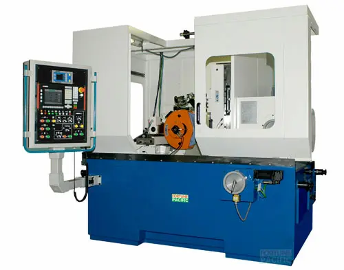
Discover the WGM360 CNC Worm Wheel Gear Grinding Machine, your ultimate precision solution for demanding gear manufacturing. This advanced CNC gear grinder delivers exceptional accuracy down to ≤0.003mm repeatability, crucial for high-tolerance worm gears used in aerospace, automotive transmissions, and heavy machinery. Featuring Siemens 840D sl CNC control, automatic wheel dressing, and precision hydrostatic spindles, it ensures superior surface finish and extended wheel life. Key specs include max wheel diameter Ø400mm, workpiece diameter up to Ø360mm, and module range M1-M10. Its rigid cast iron construction minimizes vibration, enhancing gear tooth profile accuracy and reducing noise in final applications. Operators benefit from intuitive programming, automatic tool compensation, and reduced setup times, maximizing productivity for batch production of helical gears, worm shafts, and double enveloping worm wheels. Invest in German-engineered reliability for flawless gear grinding results. Russian: Высокоточный зубошлифовальный станок WGM360 с ЧПУ предназначен для финишной обработки червячных колес и шестерен с повторяемостью ≤0,003 мм. Эта CNC машина (ЧПУ станок для шлифовки зубьев) оснащена системой Siemens 840D sl, гидростатическими шпинделями и автоматической правкой шлифкруга (алмазным карандашом), гарантируя идеальный профиль зуба и минимальный шум в зацеплении. Обрабатывает заготовки Ø360 мм, модуль M1-M10. Жесткая чугунная станина подавляет вибрации, обеспечивая высокое качество поверхности. Незаменим для аэрокосмической отрасли, коробок передач и редукторов. "Червячная пара" после WGM360 работает плавно и долговечно. Автоматизация сокращает время переналадки для серий. Spanish: La rectificadora CNC WGM360 para ruedas helicoidales y coronas sinfín ofrece precisión extrema (≤0,003mm) para engranajes críticos en automoción, aeroespacial e industria pesada. Equipada con control Siemens 840D sl, rectificado automático de muela y husillos hidrostáticos, garantiza acabados superficiales perfectos y máxima vida útil de la muela. Capacidad: Ø360mm diámetro pieza, módulo M1-M10. Su robusta estructura de fundición minimiza vibraciones, asegurando la exactitud del perfil del diente y reduciendo ruido en aplicación. Ideal para producción serie de engranajes helicoidales, tornillos sinfín y coronas globoide. Operación intuitiva, compensación automática de herramienta y cambio rápido de setup mejoran drásticamente la productividad. Solución llave en mano para rectificado de engranajes de alta gama. Portuguese: A retificadora CNC WGM360 para engrenagens cilíndricas e coroas de roda sem-fim é a máquina definitiva para usinagem de precisão (repetibilidade ≤0,003mm) exigida por setores como aeroespacial, automotivo (câmbios) e máquinas pesadas. Comando Siemens 840D sl, dressador automático de rebolo e fusos hidrostáticos garantem acabamento superior e vida longa do rebolo. Capacidade máxima: peça Ø360mm, módulo M1-M10. Estrutura rígida em ferro fundido minimiza vibração, assegurando perfil correto do dente e baixo ruído operacional. Perfeita para produção em série de engrenagens helicoidais, parafusos sem-fim e coroas globóides. Automação reduz tempo de setup e aumenta produtividade. Máquina robusta para retificação de engrenagens de alta performance. Indonesian: Mesin Gerinda CNC Roda Gigi Cacing WGM360 menyediakan solusi presisi tinggi (akurasi ≤0,003mm) untuk pembuatan roda gigi worm (worm wheel) dan worm shaft di industri aerospace, otomotif (transmisi), dan alat berat. Dilengkapi kontrol Siemens 840D sl, dressing roda gerinda otomatis, dan spindle hidrostatik, menghasilkan finishing permukaan sempurna dan umur roda gerinda panjang. Kapasitas: benda kerja Ø360mm, modul M1-M10. Konstruksi besi cor kaku meminimalkan getaran, memastikan profil gigi akurat dan reduksi kebisingan. Cocok untuk produksi massal gigi heliks, worm gear set, dan worm wheel globoid. Kemudahan operasi, kompensasi otomatis, dan setup cepat meningkatkan produktivitas. Investasi tepat untuk mesin bubut gerinda roda gigi presisi tinggi dan andal. Persian: دستگاه سنگزنی چرخدنده مارپیچ CNC مدل WGM360 با دقت تکرارپذیری ≤0.003 میلیمتر، راهحل نهایی برای تولید چرخدندههای حساس در صنایع هوافضا، خودروسازی (گیربکس) و ماشینآلات سنگین است. مجهز به کنترل Siemens 840D sl، سیستم اصلاح سنگ خودکار و اسپیندلهای هیدرواستاتیک، کیفیت سطح عالی و عمر طولانی سنگ را تضمین میکند. حداکثر قطر قطعه کار: Ø360 میلیمتر، محدوده مدول M1-M10. ساختار محکم چدنی ارتعاش را کاهش داده، دقت پروفیل دندانه و کاهش صدای چرخدنده را ممکن میسازد. ایدهآل برای تولید انبوه چرخدندههای مارپیچ، چرخدنده حلزونی و چرخدندههای گلبوئیدی. رابط کاربری آسان و اتوماسیون، زمانهای راهاندازی و تنظیم را کاهش میدهد. ماشین سنگزنی چرخ دنده حلزونی با کیفیت آلمانی. Vietnamese: Máy Mài Bánh Vít CNC WGM360 đạt độ chính xác cực cao (lặp lại ≤0.003mm) cho sản xuất bánh vít (worm wheel), trục vít (worm shaft) dùng trong hàng không, ô tô (hộp số) và máy móc hạng nặng. Trang bị hệ điều khiển Siemens 840D sl, hệ đánh bóng đá mài tự động, trục chính thủy tĩnh đảm bảo bề mặt hoàn thiện hoàn hảo và tuổi thọ đá dài. Gia công phôi Ø360mm, modun M1-M10. Kết cấu gang cứng vững giảm rung, đảm bảo biên dạng răng chính xác và vận hành êm. Lý tưởng cho sản xuất hàng loạt bánh răng xoắn, bộ truyền trục vít-bánh vít và bánh vít cầu. Vận hành trực quan, bù dao tự động và thiết lập nhanh tăng năng suất. Máy mài bánh răng CNC Đức chất lượng cao, độ tin cậy tuyệt đối. Thai: เครื่องกลึงเกียร์เวิร์ม CNC รุ่น WGM360 ให้ความแม่นยำ≤0.003mm สำหรับผลิต Worm Wheel และ Worm Shaft ในอุตสาหกรรมอากาศยาน ยานยนต์ (เกียร์) และเครื่องจักรหนัก ควบคุมด้วยระบบ Siemens 840D sl พร้อมลับคมล้อตัดอัตโนมัติและสปินเดิลไฮโดรสแตติกส์ ช่วยให้ผิวงานสมบูรณ์แบบและยืดอายุล้อตัด รับชิ้นงานขนาด Ø360mm โมดูล M1-M10 โครงสร้างเหล็กหล่อลดการสั่นสะเทือน รักษารูปฟันเกียร์ที่ถูกต้องและลดเสียงรบกวน เหมาะสำหรับผลิตเกียร์เฮลิคอล ชุดเกียร์เวิร์ม และ Globoid Worm Wheel แบบมวลชน การใช้งานง่าย ชดเชยเครื่องมืออัตโนมัติ และตั้งเครื่องเร็ว เพิ่มผลผลิตอย่างมาก เครื่องกลึงเกียร์ CNC คุณภาพเยอรมัน เชื่อถือได้สูง. Malay: Mesin Pengisar Gear CNC Worm Wheel WGM360 menawarkan ketepatan ≤0.003mm untuk pembuatan gear worm (worm gear) dalam aeroangkasa, automotif (gearbox) dan jentera berat. Dilengkapi kawalan Siemens 840D sl, pelaras roda pengisar automatik dan spindle hidrostatik, memastikan permukaan licin dan hayat roda panjang. Kapasiti: kerja Ø360mm, modul M1-M10. Binaan besi tuang tegar mengurangkan getaran, mengekalkan profil gigi tepat dan mengurangkan bunyi. Sesuai untuk pengeluaran besar-besaran gear heliks, set gear cacing dan gear globoid. Antara muka mesin CNC mesra pengguna, pampasan alat automatik dan persediaan pantas meningkatkan produktiviti. Pelaburan terbaik untuk mesin pengisar gear berketepatan tinggi dan jentera pengisar gear CNC yang tahan lasak.