| Items | TK6916A |
| Boring spindle diameter | Ф160mm |
| Spindle taper | ISO 50 |
| Main motor power- servo motor | 51kW |
| Spindle speed | 2-1250rpm |
| Max. Torque of boring head | 5000Nm |
| Size of ram section | 480X580mm |
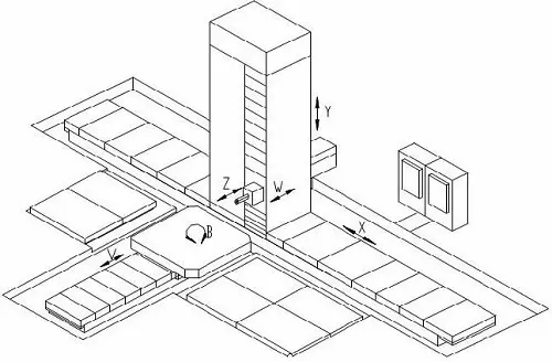
| Travel | |
| Longitudinal travel of column ( X axis) | 4000+n*1000mm (4-30m) |
| Vertical travel of boring head (Y axis) | 3000-5000mm |
| Boring spindle travel (Z axis) | 900mm |
| Ram travel (W axis) | 1100mm |
| Feeding speed | |
| Feeding speed of column longitudinal ( X axis) | 1~3000mm/min |
| Feeding speed of boring head (Y axis) | 1~3000mm/min |
| Feeding speed of boring spindle (Z axis) | 1~2000mm/min |
| Feeding speed of ram(W axis) | 1~2000mm/min |
| Rapid travel speed (X axis) | 8000mm/min |
| Rapid travel speed (Y axis) | 6000mm/min |
| Rapid travel speed (Z/W axis) | 4000mm/min |
| Accuracy and Repetitive positioning accuracy | |
| X, Y axis positioning accuracy | ±0.025/1000mm |
| Z, W positioning accuracy | ±0.03/1000mm |
| X, Y repetitive positioning accuracy | ±0.020/1000mm |
| Z, W repetitive positioning accuracy | ±0.025/1000mm |
| Item 01 | Descriptions | |
| 01.01 | SIEMENS840Dsl | |
| 01.02 | Manual pulse generator | |
| 01.03 | Automatic lubrication system | |
| 01.04 | Automatic hydraulic clamping system | |
| 01.05 | X axis guide-way cover | |
| 01.06 | Y axis guide-way cover | |
| 01.07 | Balancing and accuracy compensation mechanism | |
| 01.08 | X/Y/Z liner axis | |
| 01.09 | Tri-color light | |
| 01.10 | Work lamp | |
| 01.11 | Foundation bolts and pads |
| Item 02 | Descriptions | |
| 02.01 | Rotary table | |
| 02.02 | Face plate | |
| 02.03 | Right angle milling head | |
| 02.04 | Universal milling head | |
| 02.05 | Floor bed | |
| 02.06 | 40 or 60 stations ATC |
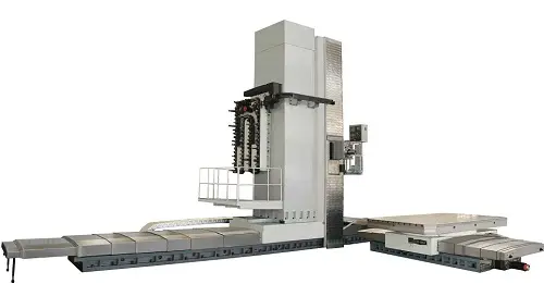
The FORTUNE PACIFIC TK6916 CNC Floor Type Boring and Milling Machine is a heavy-duty powerhouse engineered for large-scale, high-precision machining. This robust floor boring mill features a rigid box-in-box column structure and a 1-meter diameter precision rotary table capable of handling massive workpieces up to 100 tons. Powered by a high-torque spindle motor with Φ130mm quill and precise 0.01mm positioning accuracy, it excels in critical boring, milling, facing, drilling, and tapping operations on molds, frames, housings, and heavy machinery components. Key specs include X/Y/Z travels of 8000/3500/1500mm, optional digital twin ball screw drive or gear/rack systems, and Siemens or Fanuc CNC controls. Its modular design offers customization like automatic tool changers (ATC), ram cooling systems, and W-axis extensions. Advantages include exceptional rigidity minimizing vibration, superior surface finish, reduced setup times boosting productivity, and proven reliability for continuous operation in demanding industries like energy, shipbuilding, aerospace, and heavy equipment manufacturing. Engineered for maximum metal removal rates and long-term durability.
Фрезерно-расточный станок с ЧПУ FORTUNE PACIFIC TK6916 напольного типа — это решение для высокоточной обработки крупногабаритных деталей. Мощный карусельно-фрезерный станок (координатно-расточной станок) оснащен жесткой коробчатой станиной и поворотным столом диаметром 1 метр, выдерживающим детали до 100 тонн. Шпиндель Φ130 мм с высоким крутящим моментом обеспечивает точность позиционирования 0,01 мм, идеален для глубокого растачивания, фрезеровки, сверления и нарезания резьбы в энергомашиностроении, судостроении и авиакосмической отрасли. Основные параметры: Х/Y/Z=8000/3500/1500 мм, выбор привода (ШВП или шестерня/рейка), ЧПУ Siemens/Fanuc. Возможна комплектация магазином инструмента (АТС), системой охлаждения шпиндельной бабки, осью W. Ключевые преимущества: исключительная жесткость конструкции для виброустойчивости, высокая чистота поверхности, сокращение вспомогательного времени, надежность в непрерывном производстве. Станок для интенсивной обработки металла с минимальным временем простоя.
La máquina de fresado y mandrinado de piso CNC FORTUNE PACIFIC TK6916 es un centro de mecanizado pesado para piezas de gran tamaño y alta precisión. Este robusto mandrinadora-fresadora de piso cuenta con estructura de columna tipo "caja dentro de caja" y mesa rotativa de 1 metro de diámetro para piezas de hasta 100 toneladas. Su husillo de alta potencia (Φ130 mm) y precisión de posicionamiento de 0,01 mm la hacen ideal para operaciones críticas de mandrinado profundo, fresado plano, taladrado y roscado en moldes, bastidores, bancadas y componentes para energía, construcción naval, aeroespacial y maquinaria pesada. Viajes: X/Y/Z 8000/3500/1500 mm. Opciones: transmisión por tornillo de bolas o cremallera, controles CNC Siemens/Fanuc, cambiador automático de herramientas (ATC), refrigeración del cabezal, eje W. Ventajas clave: rigidez excepcional para minimizar vibraciones, acabado superficial superior, reducción de tiempos de preparación (setup), alta productividad y fiabilidad probada en operación continua. Máquina para máxima remoción de material y máxima durabilidad.
A máquina de mandrilar e fresar de piso CNC FORTUNE PACIFIC TK6916 é um equipamento robusto para usinagem de grande porte e alta precisão. Esta poderosa mandrilhadora-fresadora de piso possui estrutura rígida "box-in-box" e mesa rotativa de 1 metro de diâmetro para peças de até 100 toneladas. Com eixo-árvore de alto torque (Φ130 mm) e precisão de posicionamento de 0,01 mm, é perfeita para mandrilamento profundo, fresamento frontal, furação e rosqueamento em moldes, estruturas, carcaças e componentes para setores de energia, construção naval, aeroespacial e máquinas pesadas. Cursos: X/Y/Z 8000/3500/1500 mm. Opções: acionamento por fuso de esferas ou cremalheira/engrenagem, CN Siemens/Fanuc, trocador automático de ferramentas (ATC), refrigeração da broca, eixo W. Vantagens: rigidez excepcional contra vibração, ótimo acabamento superficial, redução de tempo de setup, alta produtividade e confiabilidade em operação contínua. Máquina para máxima remoção de cavaco e vida longa em ambientes severos. Solicite cotação para seu projeto específico.
Mesin Bor & Penggilingan Lantai CNC FORTUNE PACIFIC TK6916 adalah mesin berat untuk pengerjaan presisi tinggi pada benda kerja besar. Mesin bor-frais lantai (mesin boring milling floor type) yang tangguh ini memiliki struktur kolom kokoh dan meja putar presisi diameter 1 meter, mampu menangani benda kerja hingga 100 ton. Dilengkapi spindle motor torsi tinggi (Φ130mm) dan akurasi posisi 0,01mm, sangat unggul untuk operasi pengeboran dalam, penggilingan permukaan, pengeboran & penyadapan pada cetakan, rangka, rumah mesin, dan komponen alat berat di bidang energi, galangan kapal, dirgantara, dan manufaktur. Spesifikasi kunci: perjalanan X/Y/Z 8000/3500/1500mm, pilihan penggerak sekrup bola digital atau sistem gigi/rel, kontrol CNC Siemens/Fanuc. Desain modular memungkinkan penyesuaian seperti pengganti alat otomatis (ATC), sistem pendingin ram, dan ekstensi sumbu W. Keunggulan: kekakuan luar biasa meminimalkan getaran, hasil permukaan halus, waktu penyiapan lebih cepat meningkatkan produktivitas, dan keandalan terbukti untuk operasi terus-menerus. Mesin untuk tingkat penghilangan logam maksimal dan ketahanan jangka panjang. Dapatkan penawaran harga mesin bor milling berkualitas.
دستگاه فرز و بورینگ کف CNC فورچون پاسیفیک مدل TK6916 یک دستگاه سنگین صنعتی برای ماشینکاری دقیق قطعات بزرگ میباشد. این دستگاه بورینگ فرز کف (دستگاه دریل فرز سنگین کف) دارای ساختار ستونی جعبه در جعبه فوق مستحکم و میز گردان دقیق به قطر 1 متر بوده و قابلیت پردازش قطعات تا 100 تن را دارد. مجهز به اسپیندل موتوری با گشتاور بالا (Φ130mm) و دقت موقعیتیابی 0.01mm، جهت عملیات حیاتی بورینگ عمیق، فرزکاری سطح، دریلینگ و رزوهزنی بر روی قالبها، شاسیها، پوستهها و قطعات ماشینآلات سنگین در صنایع انرژی، کشتیسازی، هوافضا و تولید تجهیزات صنعتی سنگین ایدهآل است. مشخصات کلیدی: محدوده حرکتی محورهای X/Y/Z: 8000/3500/1500mm، گزینههای سیستم محرکه (بال اسکرو دیجیتال یا سیستم چرخ دنده و رک)، کنترلر CNC زیمنس یا فانوک. طراحی ماژولار امکان سفارشیسازی مانند مجهز به سیستم تعویض ابزار اتوماتیک (ATC)، سیستم خنککننده اسپیندل و محور W توسعهیافته را فراهم میکند. مزایا: صلبیت استثنایی جهت کاهش لرزش، پرداخت سطح عالی، کاهش زمان راهاندازی و افزایش بهرهوری، قابلیت اطمینان اثبات شده برای کار مداوم. دستگاهی با نرخ بالای برادهبرداری و دوام طولانیمدت. درخواست پیشفاکتور برای نیازهای خاص شما.
Máy phay Doa sàn CNC FORTUNE PACIFIC TK6916 là thiết bị gia công cỡ lớn, độ chính xác cao. Máy doa phay sàn (máy phay doa công nghiệp hạng nặng) cứng vững với kết cấu cột "hộp trong hộp" và bàn xoay chính xác đường kính 1m, gia công phôi tới 100 tấn. Trục chính mô-men xoắn cao (Φ130mm), độ chính xác định vị 0.01mm, vượt trội trong doa sâu, phay mặt, khoan, taro khuôn, khung, vỏ máy và chi tiết máy công trình, năng lượng, đóng tàu, hàng không vũ trụ. Hành trình X/Y/Z: 8000/3500/1500mm. Tùy chọn: truyền động trục vít me bi hoặc bánh răng/thanh răng, điều khiển CNC Siemens/Fanuc, bộ đổi dao tự động (ATC), làm mát trục chính, trục W mở rộng. Ưu điểm: độ cứng vượt trội giảm rung, bề mặt gia công mịn, giảm thời gian chuẩn bị, năng suất cao, độ tin cậy cho vận hành liên tục. Máy tối ưu tốc độ cắt gọt phôi và tuổi thọ lâu dài. Yêu cầu báo giá máy doa phay CNC chất lượng cao cho nhu cầu cụ thể.
เครื่องกัดและไสแบบตั้งพื้น CNC FORTUNE PACIFIC TK6916 เป็นเครื่องจักรอุตสาหกรรมสำหรับชิ้นงานขนาดใหญ่ ความแม่นยำสูง เครื่องไสกัดพื้น (เครื่องกัดไสหนัก) แข็งแรงทนทาน โครงสร้างคอลัมน์แบบบ็อกซ์อินบ็อกซ์ พร้อมโต๊ะหมุนแม่นยำขนาด 1 เมตร รองรับชิ้นงานหนักสูงสุด 100 ตัน ใช้มอเตอร์สปินเดิลแรงบิดสูง (Φ130mm) ความแม่นยำตำแหน่ง 0.01mm เหมาะสมสำหรับงานไสลึก กัดผิวเรียบ เจาะ และต๊าปชิ้นงานขนาดใหญ่ เช่น แม่พิมพ์ โครงสร้าง ฐานเครื่อง และชิ้นส่วนอุตสาหกรรมหนัก พลังงาน อู่เรือ อวกาศ การบิน พารามิเตอร์หลัก: ความยาวเคลื่อนที่ X/Y/Z 8000/3500/1500mm ระบบขับเคลื่อนแบบสกรูบอลหรือเกียร์/แร็ค ระบบควบคุมซีเอ็นซี Siemens/Fanuc ออกแบบโมดูลาร์ เพิ่มอุปกรณ์เสริมได้ เช่น ระบบเปลี่ยนมีดอัตโนมัติ (ATC) ระบบหล่อเย็นสปินเดิล เพิ่มแกน W ประโยชน์หลัก: ความแข็งแกร่งสูง ลดการสั่นสะเทือน พื้นผิวงานเรียบ ลดเวลาเซ็ตอัพ เพิ่มผลผลิต เชื่อถือได้สำหรับการทำงานต่อเนื่อง เครื่องจักรประสิทธิภาพสูง คงทนยาวนาน สนใจขอราคาเครื่องไสกัด CNC คุณภาพสูงสำหรับงานเฉพาะทาง。
Mesin Penggerek & Pengilangan Lantai CNC FORTUNE PACIFIC TK6916 adalah mesin industri berat untuk kerja ketepatan tinggi pada komponen bersaiz besar. Mesin penggerak-pengilang jenis lantai (mesin bore mill berat) ini mempunyai struktur tiang "box-in-box" yang tegar dan meja putar tepat berdiameter 1 meter, mampu mengendalikan benda kerja sehingga 100 tan. Digerakkan oleh motor spindel tork tinggi (Φ130mm) dan ketepatan penentududukan 0.01mm, ia cemerlang dalam operasi menggerak dalam, pengilangan permukaan, penggerudian dan pelulasan pada acuan, kerangka, rumah dan komponen untuk industri tenaga, pembinaan kapal, aeroangkasa dan jentera berat. Spesifikasi utama: perjalanan X/Y/Z 8000/3500/1500mm, pilihan pacuan skru bola digital atau sistem gear/rak, kawalan CNC Siemens/Fanuc. Reka bentuk modular menawarkan penyesuaian seperti penukar alat automatik (ATC), sistem penyejukan ram, dan sambungan paksi W. Kelebihan: ketegaran luar biasa mengurangkan getaran, permukaan licin, masa persediaan singkat meningkatkan produktiviti, dan kebolehpercayaan terbukti untuk operasi berterusan. Mesin untuk kadar penyingkiran logam maksimum dan ketahanan jangka panjang. Dapatkan sebut harga mesin bore mill berkualiti tinggi.
A máquina de mandrilar e fresar CNC tipo bancada modelo TK6916 da Fortune Pacific é um equipamento industrial robusto para usinagem pesada de grandes componentes com alta precisão. Ideal para setores como energia, construção naval e fabricação de moldes, esta máquina oferece excelente rigidez estrutural, avançado controle numérico Siemens 840D sl e recursos como mesa giratória de 40 toneladas. Principais parâmetros: curso X 10000mm, curso Y 3500mm, curso Z 1200mm, diâmetro do fuso 160mm, precisão de posicionamento 0.01mm. Sua configuração inclui cabeçote angular, sistema de refrigeração de alta pressão e trocador automático de ferramentas (opcional). Conhecida como "mandrilhadora pesada" ou "centro de usinagem vertical para grandes peças", destaca-se pela confiabilidade em operações contínuas, capacidade de faceamento pesado e acabamento fino, atendendo demandas por eficiência na remoção de cavaco e precisão repetitiva em fundições e forjados.
Ang TK6916 CNC Floor Type Boring and Milling Machine mula sa Fortune Pacific ay isang malakas na makina para sa paggawa ng malalaking parte ng sasakyan, barko, at makinarya sa kuryente. Kilala bilang "malaking CNC boring mill" o "pantayang pang-industriya para sa mabibigat na trabaho", mayroon itong matibay na disenyo, tumpak na Siemens 840D sl control system, at malaking mesa na kayang magbuhat ng 40 tonelada. Sukat ng paggalaw: X 10000mm, Y 3500mm, Z 1200mm. Tumpak hanggang 0.01mm. Magagamit sa paggawa ng turbine housing, malalaking mold, at frame ng makina. May opsyon na palitan ng kutsilyo nang awtomatiko (ATC) at ukol sa mabigat na pagputol ng metal. Pangunahing benepisyo: matibay para sa tuloy-tuloy na operasyon, mabilis sa paggawa ng malalaking parte, at mataas ang katumpakan kahit sa mabibigat na kargada—mainam para sa mga pabrika ng aviation, construction equipment, at heavy machinery.
La fresatrice-trapanatrice CNC da banco modello TK6916 di Fortune Pacific è una soluzione industriale robusta per la lavorazione pesante di componenti di grandi dimensioni. Chiamata anche "fresatrice a portale per lavori pesanti" o "centro di lavoro verticale per officine", offre precisione elevata (0.01mm), corsa X 10000mm, Y 3500mm, Z 1200mm e tavola rotante da 40 tonnellate. Dotata di controllo Siemens 840D sl, testa orientabile e sistema di raffreddamento ad alta pressione. Ideale per settori come energia e costruzioni navali, eccelle nell'alésatura di precisione, nella fresatura di superfici complesse e nella lavorazione di getti pesanti. Punti di forza: struttura in ghisa stabilissima, manutenzione semplificata, produttività elevata anche su materiali duri come acciaio legato e ghisa sferoidale. Configurabile con cambio utensile automatico (ATC) per lavorazioni ininterrotte.
Fortune Pacific TK6916 CNC Tablalı Torna ve Freze Makinesi, enerji sektörü ve ağır sanayi için büyük parçaların hassas işlenmesinde kullanılan endüstriyel bir çözümdür. "CNC dev delik makinesi" veya "ağır tip kılavuz söküm tezgahı" olarak bilinen bu model, 10000mm X, 3500mm Y, 1200mm Z hareket mesafesi, 40 tonluk döner tabla ve 0.01mm hassasiyet sunar. Siemens 840D sl kontrol ünitesi, açılı kafa ve yüksek basınçlı soğutma sistemi ile donatılmıştır. Türbin gövdesi, döküm kalıpları ve hidrolik pres imalatı için idealdir. Avantajları: güçlü döküm gövde ile titreşimsiz kesim, yüksek talaş kaldırma kapasitesi, uzun süreli üretimde güvenilirlik. Opsiyonel takım değiştirici (ATC) ile kesintisiz işleme sağlanır.
La machine aléseuse-fraiseuse CNC de type raboteuse TK6916 de Fortune Pacific est un équipement robuste pour l'usinage lourd de grandes pièces dans les secteurs de l'énergie et de la construction navale. Appelée aussi "centre d'usinage vertical à portique fixe" ou "fraiseuse à banc fixe pour gros alésages", elle offre une précision de 0.01mm, une course X 10000mm, Y 3500mm, Z 1200mm et une table tournante de 40 tonnes. Équipée du système de commande Siemens 840D sl, d'une tête orientable et d'un refroidissement haute pression. Idéale pour le surfaçage de grandes plaques, l'alésage de précision et l'usinage de pièces moulées. Points forts: structure en fonte rigide, excellent rapport puissance/rigidité pour l'enlèvement de copeaux important, fiabilité en production intensive. Option magasin à outils automatique (ATC) disponible.
ماكينة التفريز والخراطة الأرضية من فورتيون باسيفيك موديل TK6916 هي حل صناعي قوي لتشغيل المعادن الثقيلة للأجزاء الكبيرة في صناعات الطاقة والمعدات الثقيلة. تُعرف بـ "ماكينة الخراطة الأرضية CNC" أو "مركز التشغيل الرأسي للقطع الثقيلة". تتميز بدقة 0.01 مم، ومدى حركة محوري X 10000 مم، Y 3500 مم، Z 1200 مم، وطاولة دوارة حمولة 40 طن. مزودة بنظام تحكم سيمنز 840D sl، رأس قلم قابل للزوايا، ونظام تبريد عالي الضغط. مثالية لخراطة ثقوب التوربينات، تفريز قوالب الصب الكبيرة، وتشغيل هياكل الماكينات. المزايا الرئيسية: هيكل من الحديد الزهر عالي الصلادة، قدرة قص عميقة ثابتة، موثوقية في التشغيل المستمر. تتوفر خيارات مثل نظام التلقيم الأوتوماتيكي للأدوات (ATC) للانتاج غير المنقطع.
Die TK6916 CNC-Bodenbohr- und Fräsmaschine von Fortune Pacific ist eine leistungsstarke Lösung für die Schwerbearbeitung großer Werkstücke in Energie- und Schiffbaubranchen. Bekannt als "Bohrwerk für Großteile" oder "schwere Portal-Fräsmaschine CNC", bietet sie eine Positioniergenauigkeit von 0,01mm, Verfahrwege X 10000mm, Y 3500mm, Z 1200mm und einen Drehtisch für 40 Tonnen. Ausgestattet mit Siemens 840D sl-Steuerung, schwenkbarer Frässpindel und Hochdruckkühlung. Ideal für Präzisionsbohrungen, Planfräsarbeiten und die Bearbeitung schwerer Gussteile. Vorteile: stabile Grauguss-Konstruktion für vibrationsarmes Arbeiten, hohe Zuverlässigkeit im Dauerbetrieb, effiziente Spanabnahme auch bei harten Werkstoffen wie Vergütungsstahl. Optionaler Werkzeugwechsler (ATC) für automatisierte Fertigung.
De Fortune Pacific TK6916 CNC vloerboormachine/freesmachine is een krachtige industriële oplossing voor het zwaar bewerken van grote onderdelen in sectoren zoals energie en machinebouw. Ook bekend als "zware CNC boor/freescombinatie" of "portaalfreesmachine voor grote projecten". Kenmerken: nauwkeurigheid 0.01mm, bereik X 10000mm, Y 3500mm, Z 1200mm, draaibare tafel voor 40 ton. Uitgerust met Siemens 840D sl besturing, verstelbare freeskop en hoogdrukspoelsysteem. Geschikt voor het bewerken van turbinebehuizingen, grote gietstukken en zware frames. Voordelen: stabiele gietijzeren constructie, hoge betrouwbaarheid in continue productie, efficiënte verspaning door hoog koppel bij lage toerentallen. Optioneel automatisch gereedschapswisselsysteem (ATC) beschikbaar.
Frezarko-wiertarka posadzkowa CNC TK6916 od Fortune Pacific to maszyna do ciężkiej obróbki dużych elementów w energetyce i przemyśle stoczniowym. Znana jako "ciężka wiertarka stołowa CNC" lub "frezarka portalowa do obróbki żeliwa". Oferuje dokładność pozycjonowania 0.01mm, skok X 10000mm, Y 3500mm, Z 1200mm oraz obrotowy stół 40-tonowy. Wyposażona w sterownik Siemens 840D sl, głowicę kątową i system chłodzenia wysokociśnieniowego. Idealna do wytaczania precyzyjnych otworów, frezowania płaszczyzn i obróbki odlewów. Zalety: sztywna konstrukcja z żeliwa, niezawodność w pracy ciągłej, wydajne usuwanie wiórów przy obróbce stali narzędziowej i staliwa. Opcjonalny magazyn narzędzi (ATC) do automatyzacji.
Mașina de găurit și frezat CNC pe podea TK6916 de la Fortune Pacific este o soluție robustă pentru prelucrări grele în industria energetică și construcții navale. Cunoscută ca "mașină de găurit orizontală CNC" sau "centru de prelucrare vertical pentru piese masive". Parametri: precizie 0.01mm, curse X 10000mm, Y 3500mm, Z 1200mm, masă rotativă 40 tone. Echipată cu sistem de comandă Siemens 840D sl, cap port-freză orientabil și răcire sub presiune. Ideală pentru alezare precizie, frezare frontală și prelucrări pe turnări grele. Avantaje: construcție robustă din fontă, fiabilitate în funcționare continuă, capacitate mare de avans la prelucrări intense. Opțional: schimbător automat de scule (ATC).