| Item | PM1525HC |
| Capacity | |
| Worktable travel (X axis) | 2700mm |
| Saddle travel (Y axis) | 1700mm |
| Spindle travel (Z axis) | 800mm |
| Distance from spindle nose too worktable | 200—1000mm |
| Distance between columns | 1800mm |
| Motion | |
| X axis rapid traverse rate | 15 m/min |
| Y Axis rapid traverse rate | 24 m/min |
| Z axis rapid traverse rate | 15 m/min |
| Cutting feed rate | 1 - 12,000 mm/min |
| Positioning accuracy(X/Y/Z) | 0.012/0.012/0.008 mm |
| Repeatability (X/Y/Z) | 0.008/0.008/0.006 mm |
| Work table | |
| Table size | 1500×2600mm |
| Max. table load | 8000kg |
| T-slots (width X number) | 22mm×8 |
| Main spindle | |
| Tool shank | BBT50 |
| Spindle speed | 40-8000rpm |
| Max. output torque | 352/470 N.m |
| Spindle motor power | 15/18.5 kW |
| Spindle ram section | 400mm×395mm |
| Pull stud size | P50T-I |
| Others | |
| Power required | 40kVA |
| Coolant tank capacity | 600L |
| Machine dimension (LxWxH) | 7450x5650x4000mm |
| Net weight | 18500kg |
| Item 01 | Descriptions | |
| 01.01 | FANUC 0i-MF Plus (3B) CNC System | |
| 01.02 | MPG | |
| 01.03 | 32T Tool Magazine | |
| 01.04 | Operation panel | |
| 01.05 | Pneumatic system | |
| 01.06 | Air gun +water gun | |
| 01.07 | Automatic lubricating system | |
| 01.08 | Oil skimmer | |
| 01.09 | Spindle oil cooling system | |
| 01.10 | Workpiece cooling system | |
| 01.11 | Chain type chip conveyor and chip cart | |
| 01.12 | Screw type chip conveyor | |
| 01.13 | Two-speed gearbox | |
| 01.14 | Three-axis built-in encoder feedback system | |
| 01.15 | Beam rail guard | |
| 01.16 | Bed rail guard | |
| 01.17 | Full enclosure | |
| 01.18 | Tri-color light | |
| 01.19 | Lighting devices | |
| 01.20 | Air conditioner of electric cabinet | |
| 01.21 | Standard accessories (refer to packing list) | |
| 01.22 | Technical documents (refer to packing list) | |
| 01.23 | Basal installation kit (refer to packing list) |
| Item 02 | Descriptions | Note |
| 02.01 | Fanuc oi MF (1) with β motor 15/18.5kw | |
| 02.02 | Fanuc oi MF (1) with α motor 15/18.5kw | |
| 02.03 | Fanuc oi MF (1) with α motor 22/26kw | 770/910 Nm |
| 02.04 | AICC 2 + nano smoothing | Only for MF (1), included |
| 02.05 | AICC 2 400 blocks look ahead | Only for MF (1) |
| 02.06 | CNC Program memory 2MB | Standard for MF (1) & MF (5) |
| 02.07 | G68.2 | Only for MF (1) |
| 02.08 | Manual guide i | Only for MF (1) |
| 02.09 | Manual guide oi | |
| 02.10 | M30 auto power off | |
| 02.11 | Water gun | |
| 02.12 | 380V 50HZ/415V 50 HZ /220V 60 HZ | |
| 02.13 | 415V Transformer | |
| 02.14 | Voltage stabilizer | |
| 02.15 | Heidenhain linear scale X/Y/Z | |
| 02.16 | Door lock switch | |
| 02.17 | Water gun | |
| 02.18 | Air conditioner for electric cabinet | |
| 02.19 | CTS 20 bar | ZF+ belt drive 6000RPM |
| 02.20 | CTS 30 bar | ZF+ belt drive 6000RPM |
| 02.21 | CTS 50 bar | ZF+ belt drive 6000RPM |
| 02.22 | CTS 70 bar | ZF+ belt drive 6000RPM |
| 02.23 | Fully closed guard with roof | Recommend for CTS |
| 02.24 | Oil mist collector | |
| 02.25 | Column increase 200/400mm | 400-1200mm 600-1400mm |
| 02.26 | BT50 32T tool magazine | |
| 02.27 | BT50 40T tool magazine | |
| 02.28 | BT50 60T tool magazine | |
| 02.29 | 4th axis preparation | |
| 02.30 | Right side chip conveyor | |
| 02.31 | CE standard | |
| 02.32 | Renishaw Tool measurement TS27R | |
| 02.33 | Renishaw workpiece measurement OMP60 | |
| 02.34 | Single side door open size 2200mm | |
| 02.35 | Manual 90° angle head KS-A80 | MEYA |
| 02.36 | Manual 45°Universal angle head KS-U45 | MEYA |
| 02.37 | Auto Universal head NWM-AU5A5-80 | |
| 02.38 | Auto angle head NWM-AR5-80 (Including Hydraulic station, connecting plate, head stock and system function) |
| 1. FANUC CNC system | |||||
| ● Standard ○ Optional X N/A | |||||
| No. | Item | Spec. | 0I-MF Plus | ||
| Type 1 | Type 5 | ||||
| 1 | Controlled axis | Controlled axes | 5 | 5 | |
| 2 | Additional controlled axes | 7 | 6 | ||
| 3 | Least command increment | 0.001 mm / 0.0001" | ● | ● | |
| 4 | Least input increment | 0.001 mm / 0.0001" | ● | ● | |
| 5 | Interpolation type pitch error compensation | ● | ● | ||
| 6 | Interpolation & Feed Function | 2nd reference point return | G30 | ● | ● |
| 7 | 3rd / 4th reference return | ● | ● | ||
| 8 | Inverse time feed | ● | X | ||
| 9 | Cylinderical interpolation | G07.1 | ● | ○ | |
| 10 | Bell-type acceleration/deceleration before look ahead interpolation |
● | ● | ||
| 11 | Automatic corner override | G62 | ● | ● | |
| 12 | Automatic corner deceleration | ● | ● | ||
| 13 | Manual handle feed | Max. 3unit | ● | ● | |
| 14 | Handle interruption | ● | ● | ||
| 15 | Manual handle retrace | ● | ● | ||
| 16 | Nano smoothing | AI contour control II is required. | ○ | X | |
| 17 | AICC I | 40 BLOCK | X | ● | |
| 18 | AICC II | 200 BLOCK | ● | X | |
| 19 | AICC II(Preview block number increase) | 400 BLOCK(Special hardware and AI contour control II) |
○ | X | |
| 20 | Spindle & M code Function |
M- code function | ● | ● | |
| 21 | Retraction for rigid tapping | ● | ● | ||
| 22 | Rigid tapping | G84, G74 | ● | ● | |
| 23 | Tool Function | Number of tool offsets | 400 | 400 ea | 400 ea |
| 24 | Tool nose radius compensation | G40, G41, G42 | ● | ● | |
| 25 | Tool length compensation | G43, G44, G49 | ● | ● | |
| 26 | Tool life management | ● | ● | ||
| 27 | Tool offset | G45 - G48 | ● | ● | |
| 28 | Programming & Editing Function | Custom macro | ● | ● | |
| 29 | Macro executor | ● | ● | ||
| 30 | Extended part program editing | ● | ● | ||
| 31 | Part program storage | 2MB(5120m) | ● | ● | |
| 32 | Inch/metric conversion | G20 / G21 | ● | ● | |
| 33 | Number of Registerable programs | 400 ea | 400 ea | 400 ea | |
| 34 | Number of Registerable programs | 1000 ea | ○ | ○ | |
| 35 | Optional block skip | 9 BLOCK | ● | ○ | |
| 36 | Optional stop | M01 | ● | ● | |
| 37 | Program file name | 32 characters | ● | ● | |
| 38 | Sequence number | N 8-digit | N8 digit | N8 digit | |
| 39 | Playback function | ● | ● | ||
| 40 | Addition of workpiece coordinate system | G54.1 P1 - 48 (48 pairs) | 48 pairs | 48 pairs | |
| 41 | Addition of workpiece coordinate system | G54.1 P1 - 300 (300 pairs) | ○ | ○ | |
| 42 | OTHER FUNCTIONS (Operation, setting & Display, etc) |
Embeded Ethernet | ● | ● | |
| 43 | Graphic display | Tool path drawing | ● | ● | |
| 44 | Loadmeter display | ● | ● | ||
| 45 | Memory card interface | ● | ● | ||
| 46 | USB memory interface | Only Data Read & Write | ● | ● | |
| 47 | Operation history display | ● | ● | ||
| 48 | DNC operation with memory card | ● | ● | ||
| 49 | Optional angle chamfering / corner R | ● | ● | ||
| 50 | Run hour and part number display | ● | ● | ||
| 51 | High speed skip function | ● | ● | ||
| 52 | Polar coordinate command | G15 / G16 | ● | ● | |
| 53 | Programmable mirror image | G50.1 / G51.1 | ● | ● | |
| 54 | Scaling | G50, G51 | ● | ● | |
| 55 | Single direction positioning | G60 | ● | ● | |
| 56 | Pattern data input | ● | ○ | ||
| 57 | Jerk control | AI contour control II is required. | ○ | X | |
| 58 | Fast Data server with1 GB PCMCIA card | ○ | ○ | ||
| 59 | Fast Ethernet | ○ | ○ | ||
| 60 | 3-dimensional coordinate conversion | ○ | X | ||
| 61 | Figure copying | G72.1, G72.2 | ○ | ○ | |
| 62 | Machining time stamp function | ○ | ○ | ||
| 63 | Manual Guide I with 10.4" Color TFT | ○ | ○ | ||
| 64 | Dynamic graphic display (with 10.4" screen) | ● | ● | ||
| ● Standard ○ Optional X N/A | ||||||
| No. | Item | Spec. | S828D | |||
| SW24x | SW26x | SW28x | ||||
| 1 | Controlled axis | Controlled axes | 3 axes | X, Y, Z | X, Y, Z | X, Y, Z |
| 2 | Additional controlled axes | 5 | 6+2 | 8+2 | ||
| 3 | Least command increment | 0.001mm (0.0001 inch) | ● | ● | ● | |
| 4 | Least input increment | 0.001mm (0.0001 inch) | ● | ● | ● | |
| 5 | Travel to fixed stop with Force Control | ○ | ○ | ○ | ||
| 6 | Interpolation & Feed Function | Reference point return | G75 FP=1 | ● | ● | ● |
| 7 | 2nd reference point return | G75 FP=2 | ● | ● | ● | |
| 8 | Inverse time feedrate | G93 | ● | ● | ● | |
| 9 | Helical interpolation | ● | ● | ● | ||
| 10 | Polynomial interpolation | X | X | X | ||
| 11 | Spline interpolation (A, B and C splines) | ○ | ○ | ○ | ||
| 12 | Separate path feed for corners and chamfers | ● | ● | ● | ||
| 13 | Acceleration with Jerk limitation | ● | ● | ● | ||
| 14 | Compressor for 3-axis machining | ● | ● | ● | ||
| 15 | Temperature compensation | ● | ● | ● | ||
| 16 | Look Ahead, recorded part program blocks: | Milling with MDynamics Advanced Surface | 150 | 300 | 450 | |
| 17 | Milling with MDynamics Top Surface | 600 | 600 | 600 | ||
| 18 | Look Ahead, IPO blocks, buffered: | Milling with MDynamics Advanced Surface | 50 | 100 | 150 | |
| 19 | Milling with MDynamics Top Surface | 200 | 200 | 200 | ||
| 20 | Cartesian point-to-point (PTP) travel | ● | ● | ● | ||
| 21 | TRANSMIT/cylinder surface transformation | ○ | ○ | ○ | ||
| 22 | Spindle Function | Tapping with compensating chuck/rigid tapping | ● | ● | ● | |
| 23 | Tool Function | Tool radius compensations in plane | ● | ● | ● | |
| 24 | Number of tools/cutting edges in tool list | 128/256 | 256/512 | 768/1536 | ||
| 25 | Tool length compensation | ● | ● | ● | ||
| 26 | Operation with tool management | ○ | ○ | ○ | ||
| 27 | Tool list | ● | ● | ● | ||
| 28 | Replacement tools for tool management | ○ | ○ | ○ | ||
| 29 | Monitoring of tool life and workpiece count | ● | ● | ● | ||
| 30 | Manual measurement of tool offset | ● | ● | ● | ||
| 31 | Magazine list | ● | ● | ● | ||
| 32 | Programming & Editing Function | Number of levels for skip blocks 2 | ● | ● | ● | |
| 33 | Number of levels for skip blocks 10 | ○ | ○ | ○ | ||
| 34 | Program/workpiece management | On additional plug-in CF card | ● | ● | ● | |
| 35 | On USB storage medium (e.g. disk drive, USB stick) | ● | ● | ● | ||
| 36 | On network drive | ○ | ○ | ○ | ||
| 37 | Program editor | Programming support for cycles program(Program Guide) | ● | ● | ● | |
| 38 | CNC editor with editing functions: select, copy, delete | ● | ● | ● | ||
| 39 | Programming graphics/free contour input (contour calculator) | ● | ● | ● | ||
| 40 | ShopMill Machining step programming | ○ | ○ | ○ | ||
| 41 | Technology cycles for drilling/milling | ● | ● | ● | ||
| 42 | Pocket milling free contour and islands stock removal cycle | ○ | ● | ● | ||
| 43 | Residual material detection | ○ | ○ | ○ | ||
| 44 | Access protection for cycles | ○ | ○ | ○ | ||
| 45 | Programming support can be extended, e.g. customer cycles | ● | ● | ● | ||
| 46 | 2D simulation | ● | ● | ● | ||
| 47 | 3D simulation, finished part | ○ | ○ | ○ | ||
| 48 | OTHERS FUNCTIONS (Operation, setting & Display, etc) |
Switchover: inch/metric | ● | ● | ● | |
| 49 | Manual measurement of zero/work offset | ● | ● | ● | ||
| 50 | Automatic tool/workpiece measurement | ● | ● | ● | ||
| 51 | Reference point approach, automatic/via CNC program | ● | ● | ● | ||
| 52 | Execution from USB or CF card interface on operator panel front | ● | ● | ● | ||
| 53 | Execution from network drive | ○ | ○ | ○ | ||
| 54 | 10.4" color display | ● | ● | ● | ||
| 55 | 15.0" color display | ○ | ○ | ○ | ||
| 56 | Alarms and messages | ● | ● | ● | ||
| 57 | Automatic measuring cycles | ○ | ○ | ○ | ||
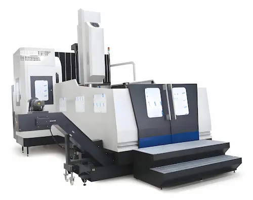
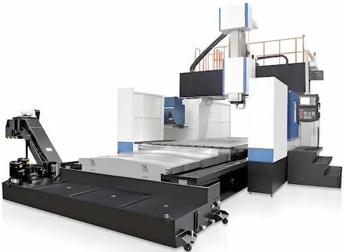
Discover the Fortune Pacific PM1525HC Double Column Machining Center engineered for ultra heavy duty milling operations This gantry style CNC machining center features a massive cast iron construction with reinforced double columns providing exceptional rigidity and vibration damping for stable high precision cutting Its large 1500mm x 2500mm worktable accommodates oversized components while the powerful 30kW BT40 spindle delivers robust performance across demanding materials like hardened steel titanium alloys and composites Key specifications include rapid traverse rates of 24m/min in all axes positioning accuracy under 5μm with laser compensated scales and an automatic 50 tool capacity magazine for uninterrupted production Essential for aerospace frames marine engine blocks and automotive die manufacturing this industrial workhorse integrates thermal symmetry technology and linear roller guides maintaining micron level accuracy during continuous 24/7 operation Industry professionals value its configurable options including 4th axis integration high pressure through spindle coolant and customized fixturing solutions that slash machining time by 40% compared to conventional mills
Откройте для себя двухколонный обрабатывающий центр Fortune Pacific PM1525HC спроектированный для сверхтяжелых фрезерных работ Этот портальный станок с ЧПУ отличается массивной чугунной конструкцией с усиленными стойками обеспечивающими исключительную жесткость и демпфирование вибраций для стабильной высокоточной обработки Большой рабочий стол 1500×2500 мм вмещает габаритные заготовки а мощный 30 кВт шпиндель BT40 гарантирует надежную работу с твердыми материалами включая инструментальную сталь титановые сплавы и композиты Ключевые параметры скорость быстрого перемещения 24 м/мин по всем осям позиционная точность 5 мкм с лазерной компенсацией и автоматический магазин на 50 инструментов для непрерывного производства Незаменим для аэрокосмических каркасов корпусов судовых двигателей и автопресс форм станок интегрирует технологию термокомпенсации и линейные роликовые направляющие сохраняя микронную точность при работе 24/7 Профессионалы ценят опции включая поворотную 4 ю ось подачу СОЖ через шпиндель под высоким давлением и специализированную оснастку что сокращает время обработки на 40% по сравнению с обычными фрезерными станками Термины как "портальный фрезерный станок" "обработка с ЧПУ" и "тяжелая фреза" улучшают поисковую видимость среди российских машиностроительных предприятий
Conozca el centro de mecanizado de doble columna Fortune Pacific PM1525HC diseñado para operaciones de fresado ultra pesadas Esta máquina CNC tipo pórtico cuenta con construcción masiva de hierro fundido y columnas dobles reforzadas que proporcionan rigidez excepcional y amortiguación de vibraciones para corte estable de alta precisión Su mesa de trabajo grande de 1500×2500 mm maneja componentes sobredimensionados mientras el husillo BT40 de 30 kW ofrece rendimiento robusto en materiales exigentes como aceros endurecidos aleaciones de titanio y compuestos Especificaciones clave incluyen avances rápidos de 24 m/min en todos los ejes precisión de posicionamiento bajo 5 μm con escalas láser compensadas y cambiador automático de herramientas para producción ininterrumpida Esencial para estructuras aeroespaciales bloques de motores marinos y moldes automotrices integra tecnología de simetría térmica y guías lineales con rodillos manteniendo precisión a nivel micrón durante operación continua 24/7 Los profesionales valoran opciones configurables como integración de 4 eje refrigerante a alta presión a través del husillo y soluciones de fijación personalizadas que reducen tiempos de mecanizado en 40% comparado con fresadoras convencionales Términos como "centro mecanizado pórtico" "fresadora pesada industrial" y "mecanizado de alta precisión" optimizan el SEO para mercados hispanohablantes
Descubra o centro de usinagem de colunas duplas Fortune Pacific PM1525HC projetado para operações de fresamento ultra pesadas Este centro CNC estilo pórtico apresenta construção maciça em ferro fundido com colunas duplas reforçadas garantindo rigidez excepcional e amortecimento de vibrações para corte estável de alta precisão Sua mesa de 1500×2500 mm acomoda componentes oversized enquanto o potente fuso BT40 de 30 kW oferece performance robusta em materiais exigentes como aços temperados ligas de titânio e compósitos Especificações técnicas incluem deslocamento rápido de 24 m/min em todos os eixos precisão de posicionamento inferior a 5 μm com escalas laser compensadas e magazine automático para 50 ferramentas garantindo produção ininterrupta Essencial para estruturas aeroespaciais blocos de motores marítimos e matrizes automotivas integra tecnologia de simetria térmica e guias lineares com roletes mantendo precisão micronétrica em operação contínua 24/7 Profissionais valorizam opções como integração de 4 eixo sistema de refrigeração interna por alta pressão e fixadores personalizados que reduzem tempo de usinagem em 40% comparado a fresadoras convencionais Termos como "centro de usinagem pórtico" "fresadora pesada industrial" e "máquina CNC para metais duros" otimizam SEO nos mercados lusófonos
Temukan Fortune Pacific PM1525HC Double Column Machining Center yang dirancang untuk operasi penggilingan ultra berat Mesin CNC gaya gantry ini memiliki konstruksi besi cor besar dengan kolom ganda yang diperkuat memberikan kekakuan luar biasa dan peredam getaran untuk pemotongan presisi tinggi yang stabil Meja kerja besar 1500×2500 mm menampung komponen oversize sementara spindle BT40 30kW memberikan kinerja kuat pada material menuntut seperti baja dikeraskan paduan titanium dan komposit Spesifikasi kunci meliputi kecepatan traverse cepat 24m/min di semua sumbu akurasi posisi di bawah 5μm dengan skala kompensasi laser dan magazine alat otomatis 50 slot untuk produksi tanpa gangguan Penting untuk bingkai aerospace blok mesin marine dan cetakan otomotif mesin ini mengintegrasikan teknologi simetri termal dan panduan roller linier mempertahankan akurasi tingkat mikron selama operasi 24/7 terus menerus Profesional menghargai opsi konfigurasi termasuk integrasi sumbu ke 4 pendingin bertekanan tinggi melalui spindle serta solusi fixture khusus yang memotong waktu pemesinan 40% dibandingkan mesin konvensional Istilah seperti "mesin gantry milling" "pusat pemesinan kolom ganda" dan "mesin CNC industri berat" meningkatkan visibilitas di pasar manufaktur Indonesia
مرکز ماشینکاری دو ستونی Fortune Pacific PM1525HC را کشف کنید که برای عملیات فرز فوق سنگین طراحی شده است این مرکز CNC با ساختار پورتیکال دارای بدنه چدنی سنگین با ستون های دوتایی تقویت شده است که سختی استثنایی و میرایی ارتعاش را برای برش پایدار با دقت بالا فراهم می کند میز کار بزرگ 1500×2500 میلی متری آن قطعات حجیم را در خود جای می دهد در حالی که اسپیندل 30 کیلوواتی BT40 عملکرد قدرتمندی را در مواد چالش برانگیز مانند فولاد سخت کاری شده آلیاژهای تیتانیوم و کامپوزیت ها ارائه می دهد مشخصات کلیدی شامل نرخ حرکت سریع 24 متر بر دقیقه در تمام محورها دقت موقعیت یابی زیر 5 میکرون با سیستم جبران ساز لیزری و مجله ابزار اتوماتیک 50 سلولی برای تولید بدون وقفه است این دستگاه ضروری برای قاب های هوافضا بلوک موتورهای دریایی و قالب سازی خودرو فناوری تقارن حرارتی و راهنماهای خطی رولری را یکپارچه می کند که دقت میکرونی را در حین کار 24 ساعته مداوم حفظ می کند متخصصان گزینه های پیکربندی از جمله ادغام محور چهارم سیستم خنک کننده فشار قوی از طریق اسپیندل و تجهیزات فیکسچر سفارشی را ارزشمند می دانند که زمان ماشینکاری را 40% نسبت به دستگاه های فرز معمولی کاهش می دهد اصطلاحات تخصصی مانند "دستگاه پورتیکال صنعتی" "مرکز فرز سنگین" و "ماشین CNC دقیق" دیدگاه سئو را در بازار ایران بهینه می کنند
Khám phá trung tâm gia công cột đôi Fortune Pacific PM1525HC được thiết kế cho hoạt động phay siêu nặng Máy CNC kiểu cổng này có kết cấu gang đúc lớn với cột đôi gia cường mang lại độ cứng vượt trội và giảm rung động để cắt chính xác cao ổn định Bàn làm việc lớn 1500×2500 mm chứa các chi tiết cỡ lớn trong khi trục chính BT40 30kW cung cấp hiệu suất mạnh mẽ trên vật liệu khó như thép tôi hợp kim titan và composite Thông số kỹ thuật chính bao gồm tốc độ chạy dao nhanh 24m/phút trên mọi trục độ chính xác định vị dưới 5μm với thang đo bù laser và bộ thay dao tự động 50 vị trí cho sản xuất liên tục Thiết yếu cho khung hàng không vũ trụ khối động cơ tàu biển và khuôn ô tô máy tích hợp công nghệ đối xứng nhiệt và dẫn hướng tuyến tính con lăn duy trì độ chính xác micron trong hoạt động liên tục 24/7 Chuyên gia đánh giá cao các tùy chọn bao gồm tích hợp trục thứ 4 hệ thống làm mát áp suất cao qua trục chính và giải pháp đồ gá tùy chỉnh giảm 40% thời gian gia công so với máy phay thông thường Thuật ngữ như "máy phay cổng công nghiệp" "trung tâm gia công cột đôi" và "máy CNC chính xác cao" tối ưu hóa SEO cho thị trường Việt Nam
รู้จักกับเครื่องจักรกลซีเอ็นซีแบบเสาคู่ Fortune Pacific PM1525HC ออกแบบมาสำหรับงานมิลลิ่งที่รับน้ำหนักสูงสุด เครื่องซีเอ็นซีสไตล์แกนทรีนี้มีโครงสร้างเหล็กหล่อขนาดใหญ่พร้อมเสาคู่ที่เสริมความแข็งแกร่งให้มีความแข็งแรงเป็นพิเศษและลดการสั่นสะเทือนเพื่อการตัดเฉือนที่มีความเสถียรและแม่นยำสูง เตียงงานขนาด 1500×2500 มม. รองรับชิ้นงานขนาดใหญ่ ในขณะที่หัวกัด BT40 กำลัง 30kW ให้สมรรถนะสูงสำหรับวัสดุที่ท้าทาย เช่น เหล็กชุบแข็ง ไทเทเนียมอัลลอยด์ และวัสดุคอมโพสิต คุณสมบัติหลักรวมถึงความเร็วเดินจังหวะเร็ว 24 ม./นาที ในทุกแกน ความแม่นยำตำแหน่งต่ำกว่า 5 ไมครอนด้วยระบบชดเชยเลเซอร์ และแมกกาซีนเก็บเครื่องมืออัตโนมัติความจุ 50 ช่อง สำหรับการผลิตต่อเนื่องไม่หยุดชะงัก เครื่องนี้จำเป็นสำหรับการผลิตชิ้นส่วนอากาศยาน ตัวเครื่องเรือ และแม่พิมพ์ยานยนต์ โดยมาพร้อมเทคโนโลยีสมมาตรความร้อนและระบบนำแนวเชิงเส้นแบบลูกกลิ้ง รักษาความแม่นยำระดับไมครอนแม้ทำงานต่อเนื่อง 24/7 ผู้เชี่ยวชาญชื่นชอบตัวเลือกการปรับแต่งรวมถึงการเชื่อมต่อแกนที่ 4 ระบบหล่อเย็นแรงดันสูงผ่านหัวกัด และอุปกรณ์จับยึดเฉพาะทางที่ลดเวลาในการตัดเฉือนลง 40% เมื่อเทียบกับเครื่องมิลลิ่งทั่วไป คำสำคัญเช่น "เครื่องมิลลิ่งแกนทรี" "เครื่องจักรกลซีเอ็นซีเสาคู่" และ "เครื่องซีเอ็นซีอุตสาหกรรม" ช่วยเพิ่มประสิทธิภาพ SEO ในตลาดไทย
Temui Mesin Pengilangan Berkolam Berkembar Fortune Pacific PM1525HC direka untuk operasi pengilangan tugas berat Pusat pemesinan CNC jenis gantry ini mempunyai struktur besi tuang besar dengan tiang berkembar diperkukuh memberikan ketegaran unggul dan redaman getaran untuk pemotongan tepat tinggi yang stabil Meja kerja besar 1500×2500 mm memuatkan komponen besar sementara spindal BT40 30kW memberikan prestasi mantap pada bahan mencabar seperti keluli dikeraskan aloi titanium dan komposit Spesifikasi utama termasuk kadar gerakan pantas 24m/min pada semua paksi ketepatan penentududukan di bawah 5μm dengan skala pampasan laser dan majalah alat automatik 50 slot untuk pengeluaran berterusan Penting untuk rangka aeroangkasa blok enjin marin dan acuan automotif ia mengintegrasikan teknologi simetri terma dan panduan gelongsor roller mengekalkan ketepatan aras mikron semasa operasi 24/7 berterusan Profesional menghargai pilihan termasuk integrasi paksi ke 4 sistem penyejuk tekanan tinggi melalui spindal dan penyelesaian pemasangan tersuai yang memotong masa pemesinan 40% berbanding kilang konvensional Istilah industri seperti "mesin gantry milling" "pusat pemesinan kolum berkembar" dan "mesin CNC ketepatan tinggi" mengoptimumkan SEO untuk pasaran Malaysia
A máquina de centro de usinagem de coluna dupla PM1525HC é um centro de maquinação vertical de alta precisão e grande porte. Sua estrutura rígida em portal (estrutura de pórtico) proporciona estabilidade excepcional para usinagem pesada e trabalhos com peças grandes. Equipada com um cabeçote de alta potência (12.000 rpm) e sistema de troca automática de ferramentas (24 posições), atende indústrias como moldes e matrizes, aeroespacial e componentes automotivos. Seus cursos generosos (X 3200mm, Y 2600mm, Z 1000mm) e mesa robusta (1500x2500mm) permitem manuseio eficiente de grandes blocos. A precisão de posicionamento é garantida em ±0.005mm/1000mm, essencial para fresamento de alta precisão e acabamento superficial superior. A construção com guias lineares nas três direções assegura rigidez, durabilidade e movimentos suaves. Controles CNC avançados, sistema de refrigeração eficiente e opções de automação integrada aumentam a produtividade e confiabilidade desta máquina-ferramenta industrial essencial para manufatura avançada.
Ang PM1525HC Double Column Machining Center ay isang malakas at tumpak na vertical machining center (VMC) na idinisenyo para sa malalaking workpiece at mabibigat na operasyon. Ang matibay na double column structure (gantry frame) nito ay nagbibigay ng kahusayan sa stability para sa heavy-duty machining at large-part manufacturing. Gamit ang high-speed spindle (hanggang 12,000 rpm) at automatic tool changer (24 tools), mainam ito para sa aerospace parts, malalaking mold, at automotive components. Malaki ang working area nito (X 3200mm, Y 2600mm, Z 1000mm) at kayang tanggapin ang mga malalaking bloke sa solid worktable (1500x2500mm). Tinitiyak nito ang mataas na katumpakan (±0.005mm/1000mm positioning accuracy) at mahusay na surface finish, mahalaga para sa precision milling. Ang linear guides sa lahat ng axes ay nagpapatibay sa rigidity at nagpapadali sa smooth na operasyon. Kasama ang advanced CNC control, efficient coolant system, at mga opsyon para sa automation, ito ay isang highly productive at reliable na industrial machine para sa mga pabrika.
Il centro di lavoro a montanti paralleli PM1525HC è una fresatrice verticale CNC di grandi dimensioni per lavorazioni pesanti e di alta precisione. La robusta struttura a portale garantisce stabilità eccezionale per la fresatura pesante su componenti di grandi dimensioni. Dotato di un mandrino ad alta velocità (12.000 giri/min) e cambio utensile automatico (24 posizioni), è ideale per stampi e matrici, settore aerospaziale e componentistica automotive. Gli ampi corsi (X 3200mm, Y 2600mm, Z 1000mm) e il solido piano di lavoro (1500x2500mm) consentono la lavorazione efficiente di grezzi voluminosi. La precisione di posizionamento (±0.005mm/1000mm) è fondamentale per lavorazioni micrometriche e finiture superficiali superiori. La costruzione con guide lineari su tutti gli assi assicura rigidità, durata e movimenti fluidi. Controlli CNC avanzati, un efficiente sistema di raffreddamento e opzioni per l'automazione integrata aumentano la produttività e l'affidabilità di questo macchinario industriale essenziale per la produzione avanzata.
PM1525HC Çift Sütunlu İşleme Merkezi, büyük parçalar ve ağır kesim işlemleri için tasarlanmış yüksek hassasiyetli, güçlü bir dikey işleme merkezidir. Sağlam portal yapısı (gantry frame), ağır hizmet tipi talaşlı imalat ve büyük parça üretimi için üstün kararlılık sağlar. Yüksek hızlı mil (12.000 dev/dak) ve otomatik takım değiştirici (24 takım) ile donatılmıştır; havacılık parçaları, büyük kalıplar ve otomotiv komponentleri için idealdir. Geniş çalışma alanı (X 3200mm, Y 2600mm, Z 1000mm) ve sağlam iş tablası (1500x2500mm) büyük iş parçalarını verimli bir şekilde işlemeye olanak tanır. Yüksek hassasiyet (±0.005mm/1000mm konumlama doğruluğu) ve üstün yüzey kalitesi sunar, hassas frezeleme için kritiktir. Tüm eksenlerdeki lineer kızaklar sertliği artırır ve sorunsuz operasyon sağlar. Gelişmiş CNC kontrol, etkili soğutma sistemi ve otomasyon entegrasyon seçenekleriyle bu endüstriyel makine, üretim tesisleri için yüksek verimli ve güvenilir bir çözümdür.
Le centre d'usinage à montants parallèles PM1525HC est une machine-outil verticale CNC robuste et de grande capacité pour l'usinage lourd et de haute précision. Sa structure en portique rigide offre une stabilité exceptionnelle pour le fraisage intensif de pièces de grandes dimensions. Équipé d'une broche puissante (12 000 tr/min) et d'un changeur automatique d'outils (24 positions), il est idéal pour les moules de grandes tailles, l'aérospatiale et les pièces automobiles. Ses grands courses (X 3200mm, Y 2600mm, Z 1000mm) et sa table solide (1500x2500mm) permettent l'usinage efficace de gros blocs. La précision de positionnement garantie (±0.005mm/1000mm) est essentielle pour l'usinage micrométrique et une finition de surface optimale. La construction avec guides linéaires sur les trois axes assure rigidité, durabilité et mouvements fluides. Associé à une commande CNC avancée, un système de refroidissement efficace et des options d'automatisation, ce centre d'usinage à portique offre une productivité et une fiabilité élevées pour la fabrication industrielle avancée.
مركز التشغيل الآلي العمودي المزدوج PM1525HC هو ماكينة قطع عمودية دقيقة وقوية مصممة لقطع المعادن الثقيلة ومعالجة القطع الكبيرة. هيكل البوابة الصلب (هيكل الجنتري) يوفر استقرارًا استثنائيًا لأعمال الخراطة والتفريز الثقيلة وتصنيع القطع كبيرة الحجم. مزود بمغزل عالي السرعة (12000 دورة/دقيقة) ونظام تغيير أدوات آلي (24 أداة)، وهو مثالي لتصنيع قطع الطيران، القوالب الكبيرة، ومكونات السيارات. منطقة العمل الواسعة (X 3200 مم، Y 2600 مم، Z 1000 مم) ومنضدة العمل المتينة (1500x2500 مم) تتيح تشغيل قطع العمل الضخمة بكفاءة. يضمن دقة عالية (±0.005 مم/1000 مم دقة تموضع) وجودة سطح ممتازة، وهو أمر حاسم لأعمال الفريزة الدقيقة. المسارات الخطية على جميع المحاور تعزز الصلابة وتضمن تشغيلًا سلسًا. مع نظام تحكم CNC متقدم، نظام تبريد فعال، وخيارات للتكامل الآلي، هذه الماكينة الصناعية هي حل عالي الإنتاجية والموثوقية لمصانع التصنيع المتقدمة.
Das PM1525HC Portal-Bearbeitungszentrum ist eine leistungsstarke und präzise Vertikal-Bearbeitungsmaschine (VMC) für die Bearbeitung großer Werkstücke und schwerer Schnitte. Die robuste Portalbauweise (Gantry-Struktur) bietet überragende Stabilität für die Schwerzerspanung und die Fertigung großformatiger Teile. Ausgestattet mit einem Hochgeschwindigkeitsspindel (12.000 U/min) und einem automatischen Werkzeugwechsler (24 Werkzeuge), ist es ideal für Luftfahrtteile, große Formen und Automobilkomponenten. Die großzügigen Verfahrwege (X 3200mm, Y 2600mm, Z 1000mm) und der massive Arbeitstisch (1500x2500mm) ermöglichen die effiziente Bearbeitung großer Rohlinge. Hohe Genauigkeit (±0.005mm/1000mm Positioniergenauigkeit) und hervorragende Oberflächengüte werden garantiert, entscheidend für die Präzisionsbearbeitung. Linearführungen auf allen Achsen erhöhen die Steifigkeit und gewährleisten einen ruhigen Lauf. Mit fortschrittlicher CNC-Steuerung, effizientem Kühlschmiermittelsystem und Optionen zur Automatisierung ist diese Werkzeugmaschine eine produktive und zuverlässige Lösung für die moderne Fertigung.
Het PM1525HC Portaal-Bewerkingscentrum is een krachtig en nauwkeurig verticaal bewerkingscentrum (VMC) ontworpen voor grote werkstukken en zwaar verspanend werk. De robuuste portaalconstructie (gantry-structuur) biedt uitstekende stabiliteit voor heavy-duty machining en de productie van grote onderdelen. Uitgerust met een hogesnelheidsspindel (12.000 tpm) en een automatisch gereedschapwisselaar (24 gereedschappen), is het ideaal voor luchtvaartonderdelen, grote mallen en auto-onderdelen. De royale verplaatsingen (X 3200mm, Y 2600mm, Z 1000mm) en de solide werktafel (1500x2500mm) maken efficiënte bewerking van grote blokken mogelijk. Hoge nauwkeurigheid (±0.005mm/1000mm positioneringsnauwkeurigheid) en een superieure oppervlaktekwaliteit worden gegarandeerd, cruciaal voor precisiefrezen. Lineaire geleidingen op alle assen verhogen de stijfheid en zorgen voor een soepele werking. Met geavanceerde CNC-besturing, een efficiënt koelsmeersysteem en automatiseringopties is deze industriële machine een productieve en betrouwbare oplossing voor geavanceerde productie.
Centrum Obróbcze Portalowe PM1525HC to wydajna i precyzyjna wertykalna obrabiarka CNC (VMC) zaprojektowana do obróbki dużych elementów i ciężkich prac skrawaniem. Solidna konstrukcja portalowa (ramowa) zapewnia doskonałą stabilność dla obróbki ciężkiej i produkcji wielkogabarytowych części. Wyposażone w wrzeciono wysokiej prędkości (12 000 obr/min) i automatyczną zmieniacz narzędzi (24 narzędzia), idealne do części lotniczych, dużych form i komponentów samochodowych. Duże zakresy ruchu (X 3200mm, Y 2600mm, Z 1000mm) oraz solidny stół roboczy (1500x2500mm) umożliwiają efektywną obróbkę dużych półfabrykatów. Gwarantowana wysoka dokładność (±0.005mm/1000mm dokładność pozycjonowania) i doskonała jakość powierzchni są kluczowe dla precyzyjnego frezowania. Liniowe prowadnice na wszystkich osiach zwiększają sztywność i zapewniają płynną pracę. Dzięki zaawansowanej sterownicy CNC, wydajnemu systemowi chłodzenia oraz opcjom automatyzacji, ta obrabiarka przemysłowa jest produktywnym i niezawodnym rozwiązaniem dla nowoczesnego zakładu produkcyjnego.
Centrul de Prelucrare Portal PM1525HC este o mașină verticală CNC puternică și precisă, proiectată pentru prelucrarea pieselor mari și a operațiilor grele de așchiere. Construcția portal robustă (structură gantry) oferă o stabilitate excepțională pentru prelucrări grele și fabricarea pieselor de dimensiuni mari. Echipat cu ax principal de mare viteză (12.000 rpm) și schimbător automat de scule (24 de scule), este ideal pentru piese aeronautice, matrițe mari și componente auto. Cursele generoase (X 3200mm, Y 2600mm, Z 1000mm) și masa solidă de lucru (1500x2500mm) permit prelucrarea eficientă a semifabricatelor voluminoase. Precizie ridicată (±0.005mm/1000mm precizie de poziționare) și calitate superioară a suprafeței sunt garantate, cruciale pentru frezarea de precizie. Ghidaje liniare pe toate axele măresc rigiditatea și asigură funcționare lină. Cu comandă CNC avansată, sistem eficient de răcire-ungere și opțiuni de automatizare, această mașină-unealtă industrială este o soluție productivă și fiabilă pentru fabricația avansată.
Fortunepacific PM1525HC kettős oszlopos megmunkáló központ kiválóan alkalmas nehéz megmunkálási feladatokra. Ez a nagy teljesítményű marógép 1500x2500mm-es munkaterülettel rendelkezik, 0,003mm-es pozicionálási pontossággal. Dupla oszlopos szerkezete kivételes merevséget biztosít, lehetővé téve nagy nyersdarabok precíz megmunkálását. Alkalmazása ideális repülőgép-alkatrészek, szerszámgéptartók és nagy formák gyártásánál. Fő előnyei: kiemelkedő stabilitás nagy forgatónyomaték mellett, hosszú élettartamú lineáris vezetőrendszer, energiahatékonyság. Felhasználók dicsérik a könnyű karbantarthatóságot és az SIEMENS 840D sl rendszer integrálását. Legfontosabb komponensek: magas szilárdságú öntöttvas szerkezet, hűtőrendszer chipkezeléssel, teljes védőburkolat porvédelmi IP54 besorolással. Ez a gép kulcsfontosságú a gyártási hatékonyság növeléséhez.
Το PM1525HC διπλής στήλης επεξεργαστικό κέντρο της Fortunepacific προσφέρει ανώτατη ακρίβεια 0,003mm για βαρείς εργασίες. Με εργασιακό πεδίο 1500x2500mm και ταχύτητες στροφών έως 8000rpm, αυτό το μηχάνημα χρησιμοποιείται ευρέως στην αεροδιαστημική και αυτοκινητοβιομηχανία. Βασικά πλεονεκτήματα: απίστευτη ακαμψία χάρη στη διπλή στήλη σχεδιασμό, μειωμένοι χρόνοι κύκλου, αυξημένη διάρκεια ζωής εργαλείων. Οι κύριες εφαρμογές περιλαμβάνουν επεξεργασία μεγάλων καλουπιών, γεωμετρικά πολύπλοκα εξαρτήματα και κρίσιμα μέταλλα. Οι χρήστες εκτιμούν το ενσωματωμένο σύστημα αυτοματοποιημένης λίπανσης και την προηγμένη θερμική αντιστάθμιση. Βασικές παράμετροι: ισχύς σπιντλ 30kW, βάρος μηχανήματος 32 τόνοι. Αυτή η λύση μηχανουργικής μεγιστοποιεί την παραγωγικότητα σε βιομηχανίες απαιτητικής ακρίβειας.
Fortunepacific PM1525HC dvousloupcové obráběcí centrum představuje špičkové řešení pro těžké obrábění. S pracovním polem 1500x2500mm a opakovací přesností 0,003mm exceluje ve výrobě forem, leteckých komponentů a strojních rámů. Hlavní výhody: vynikající dynamika díky dvojitému sloupci, vysokorychlostní obrábění hliníku, snížené vibrace. Konfigurace zahrnuje výkonný vřeteno 30kW, HIWIN lineární vedení a SIEMENS 840D sl ovládání. Uživatelé oceňují snadnou údržbu a robustní konstrukci odolávající těžkým podmínkám. Klíčové parametry: maximální rychlost posuvu 24m/min, nosnost stolu 10 tun. Tento stroj zajišťuje výjimečnou efektivitu při opracování rozměrných obrobků.
Fortunepacific PM1525HC двуколонен фрезовален център предлага изключителна стабилност за обработка на големи детайли. С работна площ 1500x2500mm и точност 0,003mm, машината е идеална за авиационни компоненти, форми и матрици. Основни предимства: висока твърдост на конструкцията, намалени вибрации, подобрена издръжливост на инструмента. Конфигурацията включва мощна шпиндела 30kW, автоматична система за смазване и пълна защита IP54. Ключови приложения: производство на големи метални конструкции, тежко машиностроене, прецизни инженерни компоненти. Потребителите ценят лесното програмиране и ниските експлоатационни разходи. Този модел е оптимален за повишаване на производствената ефективност.
Fortune Pacific PM1525HC dvokolonski mašinski centar dizajniran je za obradu velikih radnih komada sa preciznošću od 0,003mm. Radna površina od 1500x2500mm čini ga idealnim za vazduhoplovne komponente i alate. Ključne prednosti: izuzetna krutost konstrukcije, visoke brzine obrade, povećan vek trajanja alata. Konfiguracija uključuje Siemens 840D sl kontrolni sistem i automatski sistem za podmazivanje. Glavne komponente: visokočvrste livene gredice, linearni vodilici HIWIN, sistem za odvod strugotine. Korisnici ističu jednostavno održavanje i energetsku efikasnost. Ova mašina postavlja nove standarde u proizvodnji velikih preciznih delova.
Strojové centrum PM1525HC s dvojitým stĺpom od Fortune Pacific je špičkové riešenie pre obrábanie veľkých súčiastok. S pracovným priestorom 1500x2500mm a presnosťou 0,003mm sa používa na výrobu foriem, leteckých komponentov a strojových rámov. Hlavné výhody: vynikajúca dynamika, vysokorýchlostné obrábanie hliníka, znížené vibrácie. Konfigurácia zahŕňa výkonnú vretenovú skriňu 30kW, lineárne vedenie HIWIN a ovládanie SIEMENS 840D sl. Používatelia oceňujú jednoduchú údržbu a robustnú konštrukciu. Kľúčové parametre: maximálna rýchlosť posuvu 24m/min, nosnosť stola 10 ton. Tento stroj zabezpečuje výnimočnú efektivitu pri spracovaní veľkých obrobkov.
Fortune Pacific PM1525HC dvostupno obradno sredstvo pruža vrhunsku preciznost od 0,003mm za obradu velikih radnih komada. Radna površina od 1500x2500mm čini ga idealnim za zrakoplovne komponente i alate. Glavne prednosti: iznimna krutost konstrukcije, visoke brzine obrade, povećani vijek trajanja alata. Konfiguracija uključuje Siemens 840D sl upravljački sustav i automatski sustav za podmazivanje. Ključne komponente: visokokvalitetno lijevani nosači, linearni vodilici HIWIN, sustav za odvod strugotine. Korisnici ističu jednostavno održavanje i energetsku učinkovitost. Ova strojna oprema postavlja nove standarde u proizvodnji velikih preciznih dijelova.
Fortunepacific PM1525HC dvostebrni obdelovalni center zagotavlja vrhunsko natančnost 0,003mm za obdelavo velikih obdelovancev. Z delovnim prostorom 1500x2500mm je idealen za letalske komponente in orodja. Glavne prednosti: izjemna togost konstrukcije, visoke hitrosti obdelave, podaljšana življenjska doba orodja. Konfiguracija vključuje Siemens 840D sl krmilni sistem in avtomatski sistem za mazanje. Ključne komponente: visokokakovostni liti nosilci, linearne vodilnice HIWIN, sistem za odstranjevanje ostankov. Uporabniki poudarjajo enostavno vzdrževanje in energetsko učinkovitost. Ta stroj postavlja nove standarde v proizvodnji velikih natančnih delov.
Верстатний центр PM1525HC з подвійною колоною від Fortunepacific забезпечує надзвичайну стабільність для обробки великих деталей. З робочим полем 1500х2500мм та точністю 0,003мм верстат ідеальний для авіакомпонентів, прес-форм та штампів. Ключові переваги: висока жорсткість конструкції, знижені вібрації, покращений ресурс інструменту. Конфігурація включає потужний шпіндель 30кВт, систему автоматичного змащування та повний захист IP54. Основні застосування: виробництво великих металевих конструкцій, важке машинобудування, прецизійні інженерні компоненти. Користувачі цінують легке програмування та низьку собівартість експлуатації. Ця модель оптимальна для підвищення виробничої ефективності.