| Items | GMB1840 With Z axis 1000mm |
GMB1840 With Z axis 1250mm |
Remark |
| Machining range | |||
| Worktable (Length× Width) | 4000x1800mm | 4000x1800mm | |
| T slot (No. x width x distance) | 11x28mmx160mm | 11x28mmx160mm | |
| Max. load capacity | 10000kg | 10000kg | |
| Max. Table Travel - X | 4200mm | 4200mm | |
| Max. Slider travel - Y | 2600mm | 2600mm | |
| Max. Ram travel - Z | 1000mm | 1250mm | |
| Effective width of gantry | 2200mm | 2200mm | |
| Max. Height of the gantry | 1280mm | 1500mm | |
| Distance between vertical spindle to table surface | 285-1285mm | 250-1500mm | |
| Spindle | |||
| Drive type | Gear box | Gear box | |
| Power | 17/19.5kW | 17/19.5kW | |
| Highest speed | 3000rpm | 3000rpm | |
| Rated torque | 829Nm | 829Nm | |
| Max. torque | 936Nm | 936Nm | |
| Max. broach | 18000N | 18000N | |
| Taper | BT50 | BT50 | |
| Spindle speed control method | stepless | stepless | |
| Table system (X) | |||
| Structure type | Table movement | Table movement | |
| Guideway type | Heavy load linear guide | Heavy load linear guide | 65mm |
| Quantity of rail pair | 2 | 2 | |
| Transmission form | Planetary reducer | Planetary reducer | |
| Reduction ratio | 1:3 | 1:4 | Germany |
| Drive unit/Accuracy grade | Ball screw pair | Ball screw pair | Φ63x20/C3 |
| Saddle system (Y) | |||
| Structure type | Saddle movement | Saddle movement | |
| Guideway type | Heavy load linear guide | Heavy load linear guide | 55mm |
| Quantity of rail pair | 2 | 2 | |
| Transmission form | Planetary reducer | Planetary reducer | China |
| Reduction ratio | 1:2 | 1:3 | |
| Drive unit/Accuracy grade | Ball screw pair | Ball screw pair | Φ63x16/C3 |
| Ram system (Z) | |||
| Structure type | Ram movement | Ram movement | |
| Guideway type | Square ram (410x410mm) | Square ram (450x450mm) | |
| Transmission form | Planetary reducer | Planetary reducer | China |
| Reduction ratio | 1:2 | 1:3 | |
| Drive unit/Accuracy grade | Ball screw pair | Ball screw pair | Φ63x12/C3 |
| Feed motor (power, torque) | |||
| X servo motor | 3KW, 36Nm | 3KW, 36Nm | |
| Y servo motor | 3KW, 27Nm | 3KW, 27Nm | |
| Z servo motor | 3KW, 27Nm | 3KW, 27Nm | |
| Rapid feed speed | |||
| Table longitudinal movement X axis | 12000mm/min | 12000mm/min | |
| Saddle cross movement Y axis | 15000mm/min | 12000mm/min | |
| Ram vertical movement Z axis | 10000mm/min | 10000mm/min | |
| Cutting feed speed | |||
| Cutting feed speed X axis | 1-10000mm/min | 1-10000mm/min | |
| Cutting feed speed Y axis | 1-12000mm/min | 1-10000mm/min | |
| Cutting feed speed Z axis | 1-8000mm/min | 1-8000mm/min | |
| CNC system | |||
| System | Siemens 828D | Siemens 828D | 24 version |
| The total number of control axis | 3 axes | 3 axes | |
| Linkage control axis number | 3 axes | 3 axes | |
| Manual pulse generator | include | include | |
| Manual device with self-locking | include | include | |
| Interface | Ethernet, RS-232, CF card/USB | Ethernet, RS-232, CF card/USB | |
| Network card interface | DNC networking, data acquisition | DNC networking, data acquisition | |
| Tool magazine (Optional) | |||
| Tool holder | BT50 | BT50 | |
| Type | Chain type-32pcs | Chain type-32pcs | |
| Max. Tool weight | 18kg | 18kg | |
| Max. Tool length | 350mm | 350mm | |
| Max. Tool dia.(full) | 110mm | 110mm | |
| Max. Tool dia. (adjacent empty) | 200mm | 200mm | |
| Auxiliary function | |||
| Lubrication type of guideway pair/ball screw pair | automatic centralized lubrication | automatic centralized lubrication | |
| Operation panel | suspended | suspended | |
| Operation type of manual tool change | Control by button | Control by button | |
| Status indication | Three-colour warning lamp | Three-colour warning lamp | |
| Cooling type | External cooling | External cooling | |
| Safety door | Tempered Glass | Tempered Glass | |
| Positioning accuracy of linear axis (GB/T19362.1-2003) | |||
| X | 0.020mm | 0.025mm | |
| Y | 0.020mm | 0.020mm | |
| Z | 0.018mm | 0.020mm | |
| Repeat Positioning accuracy of linear axis (GB/T19362.1-2003) | |||
| X | 0.015mm | 0.015mm | |
| Y | 0.013mm | 0.013mm | |
| Z | 0.012mm | 0.013mm | |
| Working accuracy | |||
| Fine boring surface roughness | ≤Ra1.6 | ≤Ra1.6 | HB230~260 steel |
| Fine milling surface roughness | ≤Ra3.2 | ≤Ra3.2 | |
| Others | |||
| Electrical capacity | 30kVA | 30kVA | |
| Gas consumption of machine | 20m³/h | 20m³/h | |
| Machine air source pressure | 0.6-0.8Mpa | 0.6-0.8Mpa | |
| Machine weight (about) | 33000kg | 37000kg | |
| Machine size (LxWxH) | 10600x5700x5650mm | 12000x5600x6200mm | |
| Item 01 | Descriptions |
| 01.01 | Siemens 828D system |
| 01.02 | Taiwan spindle 6000rpm with China gear box (highest speed 3000rpm with oil cooler), BT50-190 |
| 01.03 | Taiwan X linear guide way, Y axis linear and box combination, Z square ram box guide way |
| 01.04 | Taiwan ballscrews for X, Y, Z |
| 01.05 | X axis with Germany Alpha reduction gear box, YZ axis China self make gear box |
| 01.06 | NSK bearings |
| 01.07 | Auto lubrication system |
| 01.08 | Taiwan water coolant pump |
| 01.09 | Schneider electric components |
| 01.10 | Nitrogen balance system |
| 01.11 | Air conditioner for electrical box |
| 01.12 | Water gun and air gun |
| 01.13 | Screw type chip conveyor |
| Item 02 | Descriptions |
| 02.01 | Fanuc CNC system |
| 02.02 | China auto type right angle milling head with head magazine |
| 02.03 | Taiwan auto type right angle milling head with head magazine |
| 02.04 | Taiwan chain type tool magazine with 32 tools |
| 02.05 | Germany ZF gear box with oil cooler |
| 02.06 | Siemens one system need an extra |
| 02.07 | 15 inch non-touch screen |
| 02.08 | 3-axis Fagor linear scales |
| 02.09 | Manual right angle head |
| 02.10 | Manual head exchanger |
| 02.11 | YZ reducer |
| 02.12 | CTS 2Mpa or 3Mpa or 5Mpa |
| 02.13 | Transverse chain chip conveyor (with chip collector) |
| 02.14 | Full protection |
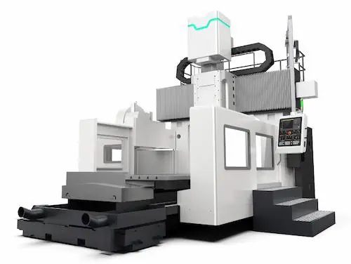
Discover the ultimate precision powerhouse with our GMB1840 CNC Gantry Milling Machine—engineered for heavy-duty industrial machining. This robust gantry-type machining center features a box-in-box structure with ultra-rigid cast iron construction, delivering unmatched stability during high-speed operations. Key specs include an 1840mm worktable, XYZ travels of 4000/2000/1000mm, BT50 spindle taper (30kW power), and 0.008mm positioning accuracy. Ideal for 5-axis machining large molds, aerospace components, and automotive frames, its linear roller guides and centralized lubrication system ensure peak efficiency and minimal downtime. Optimized for tough alloys, this industrial CNC mill offers auto tool changers (24+ tools), chip conveyors, and optional 4th-axis rotary tables. Boost productivity with superior surface finishes (±0.01mm repeatability) and energy-saving servo motors—perfect for job shops demanding high-rigidity, set-up-and-forget operation.
GMB1840 CNC портальный фрезерный станок — ваше решение для прецизионной обработки крупногабаритных заготовок. Этот высокожесткий обрабатывающий центр мостового типа оснащен чугунной станиной коробчатой конструкции и линейными роликовыми направляющими, гарантирующими виброустойчивость при скоростном резании. Технические параметры: стол 1840мм, перемещения XYZ 4000/2000/1000мм, шпиндель BT50 (30кВт), точность позиционирования 0.008мм. Применяется в аэрокосмической отрасли (лонжероны), производстве штампов и энергомашиностроении. Ключевые преимущества: система автоматической смены инструмента (24+ позиций), централизованная смазка, ЧПУ Fanuc/Siemens, опциональный поворотный стол для 5-осевой обработки. Маслоохлаждаемый шпиндель 8000 об/мин и защита от стружки обеспечивают бесперебойную работу с титаном и жаропрочными сплавами. Идеален для цехов, требующих надежности (mean time between failures >10,000 часов) и минимального обслуживания.
Maximice su producción con el centro de mecanizado puente GMB1840 CNC: una máquina de fresado industrial para piezas de gran envergadura. Fabricado en fundición de alta resistencia con estructura de caja-dentro-caja, ofrece estabilidad excepcional en operaciones de desbaste pesado. Parámetros clave: mesa 1840mm, recorridos XYZ 4000/2000/1000mm, husillo BT50 (30kW), precisión de posicionamiento ±0.008mm. Diseñado para moldes matriceros, componentes aeroespaciales y estructuras ferroviarias. Incluye cambiador automático de herramientas (24+ portabrocas), guías lineales de rodillos y sistema de refrigeración interna. Opciones como mesas giratorias de 4º eje permiten mecanizado 5 caras en una sola fijación. Ventajas clave: velocidad de avance rápido 15m/min, motor servo de bajo consumo, protección IP67 contra virutas y refrigerante. Ideal para talleres que exigen precisión repetitiva (±0.01mm) y mínimo mantenimiento. ¡Solicite hoy una demostración técnica!
Revolucione sua linha de produção com a fresadora CNC tipo pórtico GMB1840 — projetada para usinagem de alta precisão em peças maciças. Esta máquina-operatriz de ponte móvel possui estrutura rígida "box-in-box" em ferro fundido, com guias lineares de roletes para estabilidade superior. Especificações técnicas: mesa 1840mm, cursos XYZ 4000/2000/1000mm, cone BT50 (potência 30kW), repetibilidade ±0.008mm. Aplicações-chave: moldes de injeção, componentes para petróleo & gás, e estruturas navais. Equipada com trocador automático de ferramentas (24+ posições), bomba de refrigerante de alta pressão e sistema central de lubrificação. Opcionais incluem eixo rotativo para 5-sided machining e detectores de quebra de broca. Benefícios: velocidade de avanço 15m/min, consumo energético otimizado e design à prova de cavacos para operação contínua. Perfeita para indústrias metal-mecânicas que priorizam produtividade e vida útil prolongada (>15 anos).
Tingkatkan kapasitas pabrikasi logam Anda dengan mesin milling CNC gantry GMB1840 — solusi presisi tinggi untuk material besar dan berat. Mesin pusat permesinan tipe portal ini memiliki konstruksi baja tuang kokoh dengan struktur "box-in-box" dan rel geser roller linear untuk akurasi konsisten. Spesifikasi utama: meja kerja 1840mm, pergerakan XYZ 4000/2000/1000mm, spindle BT50 (30kW), ketelitian posisi 0.008mm. Cocok untuk industri otomotif (cetakan die-casting), energi (turbin), dan peralatan berat. Fitur unggulan: automatic tool changer (24+ alat), sistem pendingin spindle internal, dan pelumasan terpusat. Opsional: meja putar 4-sumbu untuk pengerjaan 5 permukaan. Keunggulan: kecepatan potong tinggi (8000rpm), perlindungan tahan tumpahan coolant, dan efisiensi energi. Pilihan tepat untuk bengkel yang membutuhkan mesin CNC industri tangguh dengan perawatan minimal.
دستگاه فرز سی ان سی پورتالی GMB1840: راهحلی ایدهآل برای ماشینکاری دقیق قطعات سنگین صنعتی. این مرکز ماشینکاری پلکلهای با ساختار جعبهدر-جعبه (box-in-box) از چدن با استحکام بالا، پایداری بینظیری در عملیات سنگین فرزکاری ارائه میدهد. مشخصات فنی: میز کار 1840 میلیمتر، محدوده حرکتی XYZ 4000/2000/1000 میلیمتر، محور اصلی BT50 (30 کیلووات)، دقت موقعیتیابی 0.008 میلیمتر. کاربردها: قالبسازی صنعتی، قطعات هوافضا و تجهیزات نیروگاهی. مجهز به سیستم تعویض ابزار خودکار (24+ ایستگاه)، راهنماهای خطی رولری، و سیستم روغنکاری مرکزی. گزینهها: میز گردان محور چهارم برای پردازش پنج وجهی. مزایا: سرعت پیشروی سریع 15m/min، موتورهای سرو کممصرف، طراحی مقاوم در برابر برادههای فلزی و خنککننده. انتخابی ایدهآل برای کارگاههایی که به دقت تکرارپذیر (±0.01mm) و قابلیت اطمینان بالا نیاز دارند.
Nâng cấp năng lực gia công với máy phay CNC cầu trục GMB1840 — giải pháp tối ưu cho chi tiết cỡ lớn. Máy phay cầu loại cổng di động có kết cấu thép đúc "box-in-box" siêu cứng vững, trục chính BT50 (30kW) đạt độ chính xác vị trí ±0.008mm. Thông số kỹ thuật: bàn làm việc 1840mm, hành trình XYZ 4000/2000/1000mm. Ứng dụng: khuôn mẫu công nghiệp, cấu kiện hàng không và máy phát điện. Trang bị bộ đổi dao tự động (24+ vị trí), hệ thống dẫn hướng con lăn và bơm làm mát áp lực cao. Tùy chọn bàn xoay trục A/C cho phay 5 mặt. Ưu điểm: tốc độ chạy dao nhanh 15m/phút, động cơ servo tiết kiệm điện, thiết kế chống phoi bào. Lựa chọn hoàn hảo cho phân xưởng cần máy CNC công nghiệp độ bền cao và bảo trì tối thiểu.
เครื่องมิลลิ่งซีเอ็นซีแบบปอร์ทัล GMB1840: โซลูชันประสิทธิภาพสูงสำหรับชิ้นงานขนาดใหญ่ โครงสร้างแบบ "box-in-box" จากเหล็กหล่อเสริมความแข็งแกร่ง พร้อมระบบนำแนวลูกกลิ้งเชิงเส้น ช่วยลดการสั่นสะเทือนขณะกัดหยาบ พารามิเตอร์หลัก: โต๊ะทำงาน 1840mm, การเคลื่อนที่ XYZ 4000/2000/1000mm, สปินเดิล BT50 (กำลัง 30kW), ความแม่นยำตำแหน่ง ±0.008mm เหมาะสำหรับอุตสาหกรรมแม่พิมพ์, ชิ้นส่วนอากาศยาน และโครงสร้างวิศวกรรม ฟีเจอร์เด่น: เครื่องเปลี่ยนมีดอัตโนมัติ (24+ ช่อง), ระบบหล่อลื่นส่วนกลาง และปั๊มน้ำหล่อเย็นแรงดันสูง ตัวเลือก: โต๊ะหมุน 4th-axis สำหรับงานกัด 5 ด้าน ข้อดี: ความเร็วป้อนเร็ว 15m/min, มอเตอร์เซอร์โวประหยัดพลังงาน, การออกแบบป้องกันเศษโลหะ คัดสรรคสำหรับโรงงานที่ต้องการเครื่องจักร CNC อุตสาหกรรมทำงานต่อเนื่องยาวนาน (>10,000 ชม.)
Tingkatkan kapasiti pengilangan anda dengan mesin penggilingan CNC gantry GMB1840 — direka untuk kerja berat industri. Mesin jenis portal ini mempunyai struktur "box-in-box" daripada besi tuang tegar dengan panduan linear galas roller, memberikan ketepatan konsisten. Spesifikasi utama: meja 1840mm, pergerakan XYZ 4000/2000/1000mm, spindal BT50 (30kW), ketepatan kedudukan ±0.008mm. Sesuai untuk acuan suntikan, komponen aeroangkasa dan struktur jentera berat. Dilengkapi penukar alat automatik (24+ stesen), sistem pelinciran berpusat dan sistem penyejuk spindal dalaman. Pilihan: meja putar 4-paksi untuk pemesinan 5 sisi. Kelebihan: kelajuan suapan 15m/min, motor servo menjimatkan tenaga, reka bentuk kalis cip. Pilihan tepat untuk bengkel yang memerlukan mesin CNC industri tahan lasak dengan penyelenggaraan minima.
Descubra a excelência em usinagem pesada com nossa Fresadora CNC Tipo Pórtico GMB1840, a solução definitiva para centros de usinagem de grande porte. Equipada com sistema FANUC ou Siemens, eixos lineares com guias de rolos e mesa fixa robusta, esta máquina-ferramenta oferece precisão micronétrica (±0.01mm) e rigidez incomparável para moldes, matrizes, componentes aeroespaciais e peças estruturais. Com curso generoso (X4000/Y2500/Z800mm), cabeçote de 6000 RPM e trocador automático de 24 ferramentas, eleva sua produtividade em operações de faceamento, fresamento 3D e usinagem de alta remoção de cavaco. A estrutura em pórtico fundido elimina vibrações, garantindo acabamento superficial impecável e vida útil prolongada — ideal para indústrias automotiva, naval e de energia. Solicite um teste de desempenho e comprove sua confiabilidade "pronto para chão de fábrica".
I-angat ang iyong produksyon sa industriya ng paggawa ng metal gamit ang aming GMB1840 CNC Gantry Type Milling Machine — isang "heavy-duty machining center" na idinisenyo para sa malalaking bahagi tulad ng molds, die casting, at mga komponente ng sasakyang panghimpapawid. Pinapagana ng FANUC o Siemens CNC controller, mayroon itong malakas na fixed table, linear roller guideways, at spindle na 6000 RPM para sa matulin at tumpak (±0.01mm) na pagputol ng bakal, aluminyo, at mga haluang metal. Ang matibay na cast iron gantry structure ay nagbibigay ng kahusayan sa paggawa ng malalim na grooves, 3D contouring, at high-speed milling. May ATC na 24 tools, malaking worktable (1840x800mm), at awtomatikong lubrication system, masisiguro mo ang minimal downtime at mataas na ROI. Perpekto para sa mga negosyong OEM at precision engineering workshop.
Trasforma la tua officina meccanica con la Fresatrice a Portale CNC GMB1840, un centro di lavoro ad alta rigidità per lavorazioni pesanti su materiali massicci. Dotata di comando FANUC o Siemens, tavola fissa rinforzata e guide lineari a rulli precaricate, garantisce precisione di ripetizione ±0.01mm e stabilità eccezionale nella lavorazione di stampi, matrici, telai industriali e componenti aerospaziali. Grazie alla struttura portale in ghisa, all’asse Z con contrappeso idraulico e al mandrino da 6000 RPM (24 utensili ATC), ottimizzerai operazioni di fresatura 3D ad alta velocità, sgrossatura aggressiva e finitura superficiale di qualità. Parametri chiave: Corsa X4000/Y2500/Z800mm, capacità di carico tavola 12,000kg. Scegli la soluzione "chiavi in mano" per officine specializzate in lavorazioni su grande formato.
GMB1840 CNC Portal Freze Makinesi ile ağır sanayi işlerinizde devrim yaratın! Bu "gantry tipi işleme merkezi", kalıpçılık, döküm kalıpları, havacılık parçaları ve büyük ebatlı iş parçaları için tasarlanmıştır. FANUC veya Siemens kontrol ünitesi, lineer rulmanlı kızaklar ve sabit masası (±0.01mm tekrarlanabilir hassasiyet) ile üstün kesme performansı sunar. 6000 RPM devirli spindle, 24 takımlı otomatik takım değiştirici (ATC) ve X4000/Y2500/Z800mm hareket menzili sayesinde yüksek hızlı frezeleme, kaba talaş kaldırma ve 3B kontur işlemede verimliliği maksimize edin. Dökme demir portal yapı, titreşimi absorbe ederek yüzey kalitesini ve makine ömrünü artırır. "Takım tezgahı" sektöründe güvenilirlik ve düşük bakım maliyeti arayanlar için ideal.
Optimisez votre production de pièces industrielles complexes avec notre Centre d’Usinage à Portique CNC GMB1840. Conçu pour l’usinage lourd de moules, matrices, composants aéronautiques et pièces surdimensionnées, ce "fraiseuse CN à portique" intègre une commande FANUC ou Siemens, des glissières à rouleaux linéaires et une table fixe robuste assurant une précision de répétition de ±0.01mm. Sa structure en fonte stabilisée, sa broche 6000 tr/min (changeur automatique 24 outils) et ses courses X4000/Y2500/Z800mm permettent des opérations de fraisage 3D haute vitesse, ébauche intensive et finition précise avec un fini de surface exceptionnel. Idéal pour l’industrie automobile, énergétique et la fabrication d’outillages, cette machine-outil garantit fiabilité "24/7" et faible coût de possession. Demandez une démonstration pour vérifier sa capacité en usinage de l’acier, titane et alliages durs.
ارتقِ بإنتاجيتك في تشغيل المعادن باستخدام آلة التفريز CNC ذات الجسر المتحرك GMB1840 - الحل الأمثل لتصنيع القوالب، الأسطمبات، المكونات الجوية والأجزاء الضخمة بدقة متناهية (±0.01 مم). مزودة بوحدة تحكم FANUC أو Siemens، قواعد توجيه خطية بمحامل أسطوانية، وطاولة ثابتة متينة لتحقيق استقرار استثنائي أثناء عمليات الخراطة والفريزة ثلاثية الأبعاد. بفضل الهيكل المصنوع من الحديد الزهر، محور دوران 6000 دورة/دقيقة، ونظام تغيير أدوات آلي (24 أداة)، تضاعف كفاءة التشغيل في التجليخ الخشن، التفريز السريع وتشطيب الأسطح. المواصفات الأساسية: شوط محوري 4000/2500/800 مم (X/Y/Z)، تحميل طاولة حتى 12 طن. مثالية لـ "مراكز التشغيل" في صناعات السيارات، الطاقة والهندسة الدقيقة. اختبر أداءها الفائق على الفولاذ، الألومنيوم والسبائك الثقيلة اليوم!
Maximieren Sie Ihre Spanleistung mit der GMB1840 Portal-Bearbeitungszentrum – die CNC-Maschine für anspruchsvolle Großteilbearbeitung in Formenbau, Luftfahrt und Schwerindustrie. Ausgestattet mit FANUC- oder Siemens-Steuerung, Linearrollenführungen und starrer Tischkonstruktion (±0.01mm Wiederholgenauigkeit) garantiert diese Werkzeugmaschine höchste Präzision bei der Bearbeitung von Stahl, Titan oder Verbundwerkstoffen. Die stabile Portalgehäusekonstruktion aus Gusseisen, 6000 U/min Spindel (24-Werkzeugmagazin) und großem Arbeitsbereich (X4000/Y2500/Z800mm) ermöglicht Hochgeschwindigkeits-Fräsen, Schruppen mit hohem Zeitspanvolumen und 3D-Konturbearbeitung ohne Verzug. Perfekt für Zerspanungsbetriebe, die auf "Standfestigkeit", geringe Wartungskosten und hohe Oberflächengüte bei der Fertigung von Großwerkzeugen oder Maschinenkomponenten Wert legen.
Boost uw productie van complexe metaalonderdelen met onze GMB1840 CNC Portaalfreesmachine – een "zware bewerkingscentrum" voor matrijzen, gietvormen, luchtvaartcomponenten en grote plaatdelen. Uitgerust met FANUC- of Siemens-besturing, lineaire rollengleidingen en een stijf tafelblad (±0.01mm herhalnauwkeurigheid), biedt deze machine gereedschap ongeëvenaarde stabiliteit bij het frezen van staal, aluminium of legeringen. Dankzij het gietijzeren portaal, 6000 tpm hoofdspil (automatische gereedschapswisselaar 24 posities) en X4000/Y2500/Z800mm verplaatsing versnelt u ruw bewerken, 3D-contourfrezen en oppervlaktefinish. Belangrijkste troeven: hoge verspaningsefficiëntie, lage trillingsgevoeligheid en minimale stilstandstijd. De ideale "machinefabriek" oplossing voor precisie-engineering, energie- en automotive sectoren. Vraag een proefbewerking aan!
Zwiększ wydajność obróbki skrawaniem dzięki Frezarce CNC Portalowej GMB1840 – maszynie do ciężkich zadań: form wtryskowych, matryc, komponentów lotniczych i wielkogabarytowych detali. Wyposażona w sterowanie FANUC lub Siemens, prowadnice rolkowe i sztywny stół (±0.01mm powtarzalność), zapewnia najwyższą precyzję przy frezowaniu stali, tytanu lub kompozytów. Solidna, żeliwna konstrukcja portalowa, wrzeciono 6000 obr/min (magazyn 24 narzędzi) i duży obszar roboczy (X4000/Y2500/Z800mm) umożliwiają wysokowydajne frezowanie 3D, głębokie rowkowanie i wykańczanie powierzchni bez drgań. Kluczowe zalety: minimalne luzów posuwowych, niskie koszty utrzymania i odporność na ciągłą pracę "w systemie 3 zmian". Idealna dla zakładów obróbczych specjalizujących się w przemyśle motoryzacyjnym, energetycznym i narzędziowym.
Revoluționați productia de piese metalice complexe cu Mașina de Frezat CNC Portal GMB1840 – o soluție "heavy-duty" pentru matrițe, forme de turnare, componente aerospațiale și prelucrări de dimensiuni mari. Echipată cu comandă numerică FANUC sau Siemens, ghidaje lineare cu rulmenți și masă fixă rigidă (±0.01mm precizie repetabilă), oferă stabilitate superioară la frezare oțel, aluminiu sau aliaje dure. Datorită construcției portale din fontă, axului principal 6000 RPM (schimbător automat de scule 24 poziții) și cursei generoase (X4000/Y2500/Z800mm), veți optimiza operațiile de degroșare, frezare 3D și finisare. Avantaje cheie: viteză de avans ridicată, precizie micronică și fiabilitate în condiții de producție continuă. Soluția ideală pentru atelierele de prelucrare din industria auto, energetică și construcții de mașini. Cereți o demonstrație live!
Ismerje meg a Fortune Pacific GMB1840 CNC portálmarógépét, a nehéz megmunkálás új szabványát! Ez a kiválóan merev, dinamikus teljesítményű portálos marógép kiváló nagy méretű alkatrészek precíz megmunkálására - acél, öntöttvas, színesfém megmunkálás ideális megoldása. Fő jellemzők: hatalmas 1840mm-es X-tengely, hidro-sztatikus vezetékek kivételes pontossághoz és hosszú élettartamhoz, erős direkt hajtású orsó 18.5kW teljesítménnyel. Hőszimmetrikus szerkezet minimális hődeformációt biztosít. Széles körű alkalmazási lehetőségek: szerszámgépek, légi- és űripari alkatrészek, formák, prototípusok gyártása. Fő előnyök: kivételes merevség nehéz megmunkáláshoz, mikronos pontosság, magas megbízhatóság, energiatakarékos szervo motorok, felhasználóbarát CNC vezérlés. Kulcsfontosságú komponensek: masszív öntöttvas szerkezet, precíziós golyósorsók, ipari Minyak hidraulika rendszer. Ez a gátlástalanul hatékony megoldás maximális termelékenységet és alacsony üzemeltetési költségeket kínál a kemény ipari feladatokhoz.
Ανακαλύψτε το Fortune Pacific GMB1840 CNC γantry τύπου μηχάνημα φρεζαρίσματος, μια κορυφαία λύση για βαρείς εργασιές! Αυτό το εξαιρετικά άκαμπτο και δυναμικό γantry φρέζα προσφέρει ακριβή επεξεργασία μεγάλων τεμαχίων - χάλυβα, χυτοσιδήρου, μη σιδηρούχων μετάλλων. Βασικά χαρακτηριστικά: τεράστιος άξονας Χ 1840mm, υδροστατικοί οδηγοί για εξαιρετική ακρίβεια και μακροζωία, ισχυρό άμεσο σπινδύλωμα 18.5kW. Θερμοσυμμετρική κατασκευή ελαχιστοποιεί θερμικές παραμορφώσεις. Ευρείες εφαρμογές: μηχανουργική, αεροδιαστημικά εξαρτήματα, καλούπια, πρωτότυπα. Κύρια πλεονεκτήματα: ακραία ακαμψία για βαριά κοπή, μικρομετρική ακρίβεια, υψηλή αξιοπιστία, ενεργειακά αποδοτικοί σερβοκινητήρες, φιλικό CNC σύστημα. Βασικά στοιχεία: μαζίβα σιδερένια κατασκευή, ακριβείς βιδωτοί άξονες με μπάλες, βιομηχανικό υδραυλικό σύστημα Minyak. Αυτή η ανυπέρβλητα αποτελεσματική λύση εξασφαλίζει μέγιστη παραγωγικότητα και χαμηλό κόστος λειτουργίας για απαιτητικές βιομηχανικές εφαρμογές.
Objevte Fortune Pacific GMB1840 CNC portálovou frézku, špičkové řešení pro těžké obrábění! Tento výjimečně tuhý a výkonný portálový obráběcí stroj zajišťuje přesné zpracování velkých obrobků – oceli, litiny, neželezných kovů. Klíčové parametry: obří osa X 1840mm, hydrostatické vedení pro vynikající přesnost a životnost, výkonný vřeteno s přímým pojezdem 18.5kW. Teplotně symetrická konstrukce minimalizuje tepelné deformace. Široké použití: strojírenství, letecké a kosmické součástky, formy, prototypy. Hlavní výhody: extrémní tuhost pro těžké frézování, mikronová přesnost, vysoká spolehlivost, úsporné servomotory, uživatelsky přívětivé CNC řízení. Klíčové komponenty: masivní litinová konstrukce, přesné kuličkové šrouby, průmyslový hydraulický systém Minyak. Toto bezkonkurenčně efektivní řešení nabízí maximální produktivitu a nízké provozní náklady pro náročné průmyslové aplikace.
Откройте за себе Fortune Pacific GMB1840 CNC готвален фрезовален център, върхово решение за тежки обработки! Тази изключително твърда и мощна портална машина предлага прецизна обработка на големи детайли - стомана, чугун, цветни метали. Основни параметри: огромна Х ос 1840мм, хидростатични водачи за отлична точност и дълъг живот, мощен шпиндел с директен задвижване 18.5kW. Топлинно-симетрична конструкция минимизира деформациите. Широк спектър на приложения: машиностроене, авиационни и космически компоненти, форми, прототипи. Основни предимства: екстремна твърдост за тежки обработки, микронна точност, висока надеждност, енергоефективни сервомотори, лесен за употреба CNC контрол. Ключови компоненти: масивна чугунена конструкция, прецизни винтове с топчета, индустриална хидравлична система Minyak. Това несравнимо ефективно решение осигурява максимална производителност и ниски експлоатационни разходи за най-требователните промишлени задачи.
Откријте Fortune Pacific GMB1840 CNC порталну глодалицу, врхунско решење за тешко обрађивање! Ова изузетно крута и снажна портална глодалица пружа прецизну обраду великих делова - челика, ливеног гвожђа, обојених метала. Кључни параметри: огромна X оса 1840мм, хидростатска водица за изузетну прецизност и дуговечност, моћно главно вретено са дирекним погоном 18.5kW. Термички симетрична конструкција минимизира топлотне деформације. Широк спектар примене: машинство, авио и свемирски делови, калупи, прототипови. Главне предности: екстремна крутост за тешко глодање, микронска прецизност, висока поузданост, енергетски ефикасни серво мотори, једноставан CNC управљачки систем. Кључне компоненте: масивна ливена конструкција, прецизни куглични завртњеви, индустријски хидраулични систем Minyak. Ово неупоредиво ефикасно решење нуди максималну продуктивност и ниске оперативне трошкове за захтевне индустријске примене.
Objavte Fortune Pacific GMB1840 CNC portálovú frézu, špičkové riešenie pre ťažké obrábanie! Tento výnimočne tuhý a výkonný portálový obrábací stroj zabezpečuje presné spracovanie veľkých obrobkov - ocele, liatiny, neželezných kovov. Kľúčové parametre: obrovská os X 1840mm, hydrostatické vedenie pre vynikajúcu presnosť a životnosť, výkonné vreteno s priamym pohonom 18.5kW. Tepelne symetrická konštrukcia minimalizuje tepelné deformácie. Široké využitie: strojárstvo, letecké a kozmické komponenty, formy, prototypy. Hlavné výhody: extrémna tuhosť pre ťažké frézovanie, mikrónová presnosť, vysoká spoľahlivosť, úsporné servomotory, užívateľsky prívetivé CNC riadenie. Kľúčové komponenty: masívna liatinová konštrukcia, presné guľkové skrutky, priemyselný hydraulický systém Minyak. Toto neprekonateľne efektívne riešenie ponúka maximálnu produktivitu a nízke prevádzkové náklady pre náročné priemyselné aplikácie.
Otkrijte Fortune Pacific GMB1840 CNC portalu glodalicu, vrhunsko rješenje za tešku obradu! Ovaj iznimno krut i snažan portalu glodalica nudi preciznu obradu velikih komada - čelika, lijevanog željeza, obojenih metala. Ključni parametri: ogromna X os 1840mm, hidrostatski vodilici za izvrsnu preciznost i dugovječnost, snažno glavno vreteno s izravnim pogonom 18.5kW. Termički simetrična konstrukcija minimizira toplinske deformacije. Široka primjena: strojogradnja, zrakoplovne i svemirske komponente, kalupi, prototipovi. Glavne prednosti: ekstremna krutost za teško glodanje, mikronska preciznost, visoka pouzdanost, energetski učinkoviti servo motori, jednostavan CNC upravljački sustav. Ključne komponente: masivna lijevana konstrukcija, precizni kuglični vijci, industrijski hidraulični sustav Minyak. Ovo usporedivo učinkovito rješenje nudi maksimalnu produktivnost i niske operativne troškove za zahtjevne industrijske aplikacije.
Odkrijte Fortune Pacific GMB1840 CNC portalno glodalni stroj, vrhunsko rešitev za težko obdelavo! Ta izjemno tog in zmogljiv portalni stroj zagotavlja natančno obdelavo velikih obdelovancev - jekla, litega železa, barvnih kovin. Ključni parametri: ogromna X os 1840mm, hidrostatski vodila za izjemno natančnost in dolgo življenjsko dobo, močan vreten s premim pogonom 18.5kW. Toplotno simetrična konstrukcija zmanjšuje toplotne deformacije. Široka uporaba: strojništvo, letalske in vesoljske komponente, orodja, prototipi. Glavne prednosti: ekstremna togost za težko glodanje, mikronska natančnost, visoka zanesljivost, varčni servomotorji, uporabniku prijazen CNC krmilnik. Ključne komponente: masivna lita konstrukcija, natančni kroglični vijaki, industrijski hidravlični sistem Minyak. Ta neprekosljivo učinkovita rešitev nudi največjo produktivnost in nizke operativne stroške za zahtevne industrijske aplikacije.
Відкрийте для себе Fortune Pacific GMB1840 CNC портальний фрезерний верстат, провідне рішення для важкої обробки! Цей надзвичайно жорсткий та потужний портальний верстат забезпечує точну обробку великих заготовок - сталі, чавуну, кольорових металів. Ключові параметри: величезна вісь X 1840мм, гідростатичні напрямні для відмінної точності та довговічності, потужний шпиндель з прямим приводом 18.5кВт. Термічно симетрична конструкція мінімізує теплові деформації. Широке застосування: машинобудування, авіаційні та космічні компоненти, форми, прототипи. Основні переваги: надзвичайна жорсткість для важкого фрезерування, мікронна точність, висока надійність, енергоефективні сервомотори, зручна CNC система керування. Ключові компоненти: міцна чавунна конструкція, прецизійні кулькові гвинти, промислова гідравлічна система Minyak. Це неперевершено ефективне рішення забезпечує максимальну продуктивність та низькі експлуатаційні витрати для вимогливих промислових завдань.