| Main parameters | Unit | WHN110 | WHN125 | WHN130 | WHN140 |
|---|---|---|---|---|---|
| CNC system | SIEMENS 840D; FANUC 31i; HEIDENHAIN iTNC 530 | ||||
| Spindle diameter | mm | 112 (4.4”) | 125 (4.9”) | 130 (5.1”) | 140 (5.5”) |
| Spindle taper | ISO50 (7:24) | ||||
| Tool pullstud | mm | 25mm (0.98”) extended on DIN 69872 | |||
| Spindle speed | r/min | 10-2800 | 10-3300 | 10-2500 | 10-3000 |
| Max. spindle torque | Nm | 2110 | 1457 | 2350 | 1622 |
| Max. workpiece weight | kg | 8000 | 12000 | ||
| Rotary table size | mm | 1250x1400; 1400x1600 (49x55; 55x63”) |
1600x1800; 1800x2240 (63x71; 71x88”) |
||
| T slot (width x No. x pitch) | mm | 22x9x160 | 22x9x160; 28x10x160 | ||
| Table travel (X) | mm | 1600; 2000; 2500 (63; 79; 98”) |
2000; 2500; 3000; 3500; 4000 (79; 98; 118; 138”) |
||
| Headstock travel (Y) | mm | 1250; 1400; 1600; 2000 (49; 55; 63; 79”) |
1600; 2000; 2500 (63; 79; 98”) |
||
| Column travel (Z) | mm | 800; 1000; 1250; 1600 (32; 39; 49; 63”) |
1000; 1250; 1600; 2000 (39; 49; 63; 79”) |
||
| Spindle travel (W) | mm | 710 (28”) | 500 (20”) | 800 (32”) | 560 (22”) |
| Min. distance of spindle axis above table | mm | 50 (2”) | |||
| Feed range of X, Y, Z and W | mm/min | 1-6000 | |||
| Feed range of B | r/min | 0.03-1.5 | |||
| Rapid traverse of X, Y, Z and W | mm/min | 10000 | |||
| Rapid traverse of B | r/min | 2.5 | 2 | ||
| Total power consumption | kVA | 83kVA (3ph, 380V, 50Hz) | |||
| Spindle motor power | kW | 37 | |||
| Tool magazine capacity | 40; 60; 80; 90 | |
|---|---|---|
| Pitch of pocket | mm | 130 (5.1”) |
| Max. tool diameter / whole tool magazine | mm | 125 / 150 (4.9 / 5.9”) |
| Gap between adjacent pocket | mm | 250 (9.8”) |
| Max. diameter of special flat tools | mm | 390 (15”) |
| Max. tool length | mm | 400 (16”) |
| Max. tool weight | kg | 25 |
| Average tool weight | kg | 15 |
| Max. unbalance loading | kg | 80 |
| Total tool change time | sec | 20 |
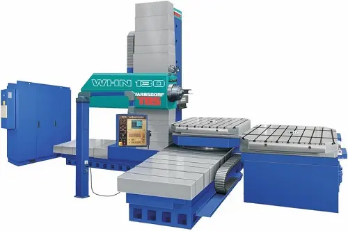
Fortune Pacific's TOS WHN110/WHN130 Horizontal Boring and Milling Machine delivers unmatched precision for heavy-duty machining. Engineered for stability with a robust cast iron structure and a powerful 130mm spindle diameter, this CNC powerhouse tackles complex components in energy, aerospace, and heavy machinery sectors. Its advanced FANUC control, linear guideways, and rotary table ensure micron-level accuracy (positioning: 0.016mm) and smooth finishes. Key specs include X/Y/Z travels up to 6000/4500/1250mm, spindle speeds to 1000 rpm, and generous table loading. Expect enhanced productivity through rigid machining of large castings, frames, and gearboxes with superior surface quality. This reliable workhorse minimizes vibration and maximizes uptime, offering exceptional value for demanding industrial applications where precision boring, milling, and facing are critical. Get robust performance and long-term ROI.
Фрезерно-расточной станок с ЧПУ TOS WHN110/WHN130 от Fortune Pacific — решение для высокоточной обработки особо крупных деталей ("обработка негабарита"). Этот тяжелый горизонтальный расточной станок (горизонтально-расточной) оснащен сверхжесткой станиной, шпинделем 130 мм и продвинутой системой ЧПУ FANUC. Идеален для энергетики, аэрокосмической отрасли и тяжелого машиностроения. Параметры: перемещения по осям X/Y/Z до 6000/4500/1250 мм, точность позиционирования 0.016 мм. Станок обеспечивает чистовую обработку ("чистовая") корпусов редукторов, станин, плит с высочайшим качеством поверхности благодаря линейным направляющим и поворотному столу. Надежная конструкция гарантирует минимальную вибрацию ("виброустойчивость") и максимальную производительность при растачивании отверстий, фрезеровании плоскостей и контуров. Ключевые преимущества: исключительная жесткость, точность обработки ("прецизионная обработка") и долгий срок службы для сложных производственных задач.
La Fresadora-Taladradora Horizontal TOS WHN110/WHN130 de Fortune Pacific es una máquina herramienta CNC robusta para mecanizado pesado de alta precisión. Con un diámetro de husillo principal de 130 mm y una estructura de fundición rígida, es ideal para el fresado, taladrado y mandrinado de piezas grandes en sectores como energía, aeroespacial y maquinaria pesada. Su control FANUC, guías lineales y mesa giratoria garantizan una precisión de posicionamiento de 0,016 mm y acabados superficiales excepcionales. Parámetros clave: recorridos X/Y/Z hasta 6000/4500/1250 mm, velocidad de husillo hasta 1000 rpm y gran capacidad de carga en mesa. Perfecta para el mecanizado de bancadas, carcasas de reductores ("cajas de engranajes") y componentes estructurales complejos. Ofrece alta productividad, fiabilidad y mínimas vibraciones, maximizando el rendimiento en operaciones de mandrinado de precisión, fresado de planos y contouring. Una inversión sólida para talleres que exigen precisión micronétrica y durabilidad en el mecanizado de piezas grandes ("mecanizado de grandes dimensiones").
A Furadeira-Fresadora Horizontal TOS WHN110/WHN130 da Fortune Pacific é uma máquina CNC poderosa para usinagem pesada de alta precisão. Com eixo principal de 130 mm de diâmetro e estrutura rígida em ferro fundido, é perfeita para fresamento, furação e mandrilamento de peças de grandes dimensões nos setores de energia, aeroespacial e máquinas pesadas. O controle FANUC, guias lineares e mesa rotativa garantem precisão de posicionamento de 0,016 mm e excelente acabamento superficial. Principais especificações: cursos X/Y/Z até 6000/4500/1250 mm, velocidade do eixo até 1000 rpm e alta capacidade de carga na mesa. Ideal para usinar bases de máquinas, carcaças de redutores ("caixas de engrenagens") e componentes estruturais complexos. Oferece alta produtividade, confiabilidade e mínima vibração, maximizando o desempenho em operações de mandrilamento de precisão, fresamento de planos e contornamento. Um centro de usinagem horizontal robusto e confiável para quem exige precisão micrônica e durabilidade no trabalho com peças grandes ("usinagem de grandes peças").
Mesin Bor-Frais Horizontal TOS WHN110/WHN130 dari Fortune Pacific adalah mesin CNC perkasa untuk pengerjaan berat berpresisi tinggi. Dengan diameter spindle utama 130 mm dan struktur besi cor yang kaku, sangat ideal untuk operasi frais, bor, dan bor membos ("boring") pada komponen besar di sektor energi, dirgantara, dan permesinan berat. Kontrol FANUC, rel linear, dan meja putar menjamin akurasi posisi 0,016 mm dan hasil permukaan yang halus. Spesifikasi kunci: langkah sumbu X/Y/Z hingga 6000/4500/1250 mm, kecepatan spindle hingga 1000 rpm, kapasitas beban meja besar. Sangat cocok untuk mengerjakan badan mesin ("bed mesin"), rumah gearbox, dan komponen struktural kompleks. Menawarkan produktivitas tinggi, keandalan, dan getaran minimal, meningkatkan kinerja dalam operasi membos presisi, perataan permukaan ("surface milling"), dan pembuatan kontur. Solusi andal untuk bengkel yang membutuhkan ketelitian mikron dan ketahanan dalam mengolah benda kerja besar ("pengerjaan benda kerja besar").
دستگاه بورینگ و فرز افقی TOS WHN110/WHN130 فورچون پسیفیک یک ماشین ابزار CNC قدرتمند برای ماشینکاری سنگین با دقت فوق العاده است. با اسپیندل اصلی 130 میلیمتری و ساختار صلب چدن خاکستری، این دستگاه ایدهآل برای عملیات فرزکاری، دریلینگ و بورینگ قطعات بزرگ در صنایعی مانند انرژی، هوافضا و ماشینسازی سنگین است. کنترل پیشرفته FANUC، راهنماهای خطی (ریل خطی) و میز گردان، دقت موقعیتیابی 0.016 میلیمتر و پرداخت سطح عالی را تضمین میکنند. مشخصات کلیدی: حرکت محورهای X/Y/Z تا 6000/4500/1250 میلیمتر، سرعت اسپیندل تا 1000 دور بر دقیقه و ظرفیت بارگذاری میز بالا. مناسب فوقالعاده برای ماشینکاری بدنه ماشینها ("بدنه دستگاه")، پوستهگیربکسها و قطعات ساختاری پیچیده. این دستگاه با نام "دستگاه بورینگ افقی دقیق" شناخته میشود و به لطف طراحی ضدلرزه ("پایه ضد ارتعاش")، بهرهوری بالا، قابلیت اطمینان و حداقل لرزش را ارائه میدهد و عملکرد را در عملیات بورینگ دقیق (سوراخکاری دقیق)، فرزکاری سطوح تخت و کانتورینگ به حداکثر میرساند. انتخابی مطمئن برای کارگاههایی که نیازمند دقت میکرونی و دوام در ماشینکاری قطعات بزرگ ("ماشینکاری قطعات سنگین") هستند.
Máy Doa & Phay ngang TOS WHN110/WHN130 của Fortune Pacific là máy CNC mạnh mẽ cho gia công tinh nặng. Với trục chính đường kính 130mm và kết cấu gang đúc cứng vững, lý tưởng cho phay, khoan, doa chi tiết lớn trong ngành năng lượng, hàng không vũ trụ và chế tạo máy hạng nặng. Điều khiển FANUC, ray trượt tuyến tính và bàn xoay đảm bảo độ chính xác định vị 0.016mm và độ nhẵn bề mặt vượt trội. Thông số chính: hành trình X/Y/Z lên tới 6000/4500/1250mm, tốc độ trục chính 1000 vòng/phút, tải trọng bàn lớn. Hoàn hảo để gia công thân máy ("vỏ máy"), hộp số ("vỏ hộp giảm tốc") và các chi tiết kết cấu phức tạp. Máy doa phay ngang CNC này mang lại năng suất cao, độ tin cậy và rung động tối thiểu, tối ưu hiệu suất trong doa lỗ chính xác, phay mặt phẳng và phay biên dạng. Lựa chọn đáng tin cậy cho các phân xưởng yêu cầu độ chính xác micron và độ bền khi gia công phôi lớn ("gia công chi tiết cỡ lớn").
เครื่องกลึงไสแนวราบ TOS WHN110/WHN130 จาก Fortune Pacific เป็นเครื่องซีเอ็นซีประสิทธิภาพสูงสำหรับงานไสกลึงชิ้นงานขนาดใหญ่ด้วยความแม่นยำขั้นสุด ด้วยสปินเดิลหลักขนาด 130 มม. และโครงสร้างเหล็กหล่อที่แข็งแรงมั่นคง เครื่องนี้เหมาะอย่างยิ่งสำหรับงานกัด ไส เจาะ และกลึงคว้าน ("กัดไส") ชิ้นส่วนขนาดใหญ่ในอุตสาหกรรมพลังงาน การบินอวกาศ และเครื่องจักรหนัก ระบบควบคุม FANUC, แนวเลื่อนแบบลิเนียร์ และโต๊ะหมุนรับประกันความแม่นยำการวางตำแหน่ง 0.016 มม. และผิวงานเรียบเนียน พารามิเตอร์หลัก: ความยาวเคลื่อนที่แกน X/Y/Z สูงสุด 6000/4500/1250 มม., ความเร็วสปินเดิลสูงสุด 1000 รอบ/นาที, และรับน้ำหนักโต๊ะได้มาก เหมาะสมอย่างยิ่งสำหรับการกลึงไสฐานเครื่อง ("โครงเครื่อง"), ตัวเร่ง ("ตัวเร่งความเร็ว") และชิ้นส่วนโครงสร้างซับซ้อน ให้ผลผลิตสูง เชื่อถือได้ และสั่นสะเทือนน้อยสุด เพิ่มประสิทธิภาพสูงสุดในงานกลึงไสเจาะรูแบบแม่นยำ ("ไสเจาะ"), งานกัดหน้าตัด และกัดเส้น轮廓 เครื่องไสแนวราบซีเอ็นซีนี้เป็นตัวเลือกที่ไว้ใจได้สำหรับโรงงานที่ต้องการความแม่นยำระดับไมครอนและความทนทานในการทำงานกับชิ้นงานขนาดใหญ่ ("งานกลึงไสชิ้นงานใหญ่").
Mesin Penggerudi dan Pengilangan Mendatar TOS WHN110/WHN130 daripada Fortune Pacific ialah mesin CNC berkuasa untuk kerja berat berketepatan tinggi. Dengan spindal utama 130mm diameter dan struktur besi tuang tegar, ia sesuai untuk operasi pengilangan, penggerudian dan penggerudian membos ("boring") komponen besar dalam sektor tenaga, aeroangkasa dan jentera berat. Kawalan FANUC, panduan linear dan meja putar menjamin ketepatan penentududukan 0.016mm dan kemasan permukaan unggul. Spesifikasi utama: pergerakan paksi X/Y/Z sehingga 6000/4500/1250mm, kelajuan spindal 1000rpm, kapasiti beban meja tinggi. Sangat sesuai untuk mengilang badan mesin ("bed mesin"), rumah gearbox dan komponen struktur kompleks. Mesin gerudi kilang mendatar CNC ini menawarkan produktiviti tinggi, kebolehpercayaan dan getaran minima, memaksimumkan prestasi dalam operasi membos ketepatan, pengilangan permukaan rata dan contouring. Pilihan dipercayai untuk bengkel yang memerlukan ketepatan mikron dan ketahanan dalam mengendalikan benda kerja besar ("kerja pengilangan benda kerja besar").