| Model | Unit | MHS500 |
|---|---|---|
| Type | C | |
| Max shaping length | mm | 500 (20”) |
| Max horizontal movement of the table | mm | 525 (21”) |
| Max distance between ram bottom and table | mm | 370 (15”) |
| Max vertical movement of the table | mm | 270 (11”) |
| Dimensions of table top: L x W | mm | 440x360 (17x14”) |
| Max stroke of the tool head | mm | 120 (4.7”) |
| Swivel angle of the tool head | ° | ±60º |
| Max section of tool: W x H | mm | 20x30 (0.79x1.2”) |
| Number of ram reciprocation per minute | 14~80 | |
| Feed range of horizontal table | mm | 0.2~2.5 |
| Feed range of vertical table | mm | 0.08~1 |
| Rapid travel speed of horizontal table | m/min | 0.95 |
| Rapid travel speed of vertical table | m/min | 0.38 |
| T-slot width for center positioning | mm | 18 (0.71”) |
| Main motor power | kW | 3 |
| Rapid travel motor power | kW | 0.55 |
| Net weight (approx) | kg | 1800 |
| Gross weight | kg | 2000 |
| Machine dimension (L x W x H) | mm | 2160×1070×1194 |
| Packing dimension (L x W x H) | mm | 1840×1200×1540 |
| Flatness of machined surface on tested workpiece | mm | 0.025 |
| Parallelism of machined surface on tested workpiece to base | mm | 0.03 |
| Parallelism of machined surface on one side to that on the other side on tested workpiece | mm | 0.05 |
| Verticality of machined side surface on the side of tested workpiece against base | mm | 0.02 |
| Surface roughness | 6.3 |
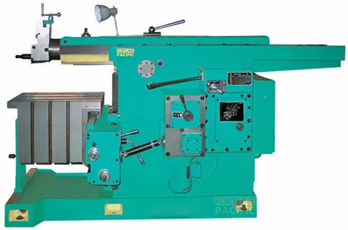
The MHS500C Mechanical Shaping Machine by Fortune Pacific is a high-precision industrial shaping equipment designed for metalworking applications. Known as a "metal shaper" or "planer machine" in the industry, this robust machine features heavy-duty cast iron construction for vibration damping. Key specifications include 500mm stroke length, 0.05mm positioning accuracy, and automatic feed system. The machine utilizes a ram-type reciprocating mechanism with adjustable speed from 20-120 strokes per minute. Common applications include keyway cutting, gear shaping, and surface finishing. Operators appreciate its "set-and-forget" reliability and "dead-on" accuracy for repetitive tasks. The machine's "bulletproof" design incorporates hardened guideways, precision ground ballscrews, and an oil-bath gearbox. For maintenance crews, the "drop-in" replacement parts system minimizes downtime.
Металлообрабатывающий станок MHS500C от Fortune Pacific - это профессиональный строгальный станок (фуганок) для точной обработки металлов. Основные характеристики: ход ползуна 500 мм, точность позиционирования 0,05 мм, автоматическая подача. В промышленности известен как "продольно-строгальный станок" или "долбежник". Особенности конструкции: чугунная станина для гашения вибраций, закаленные направляющие, шариковые винты. Применяется для создания пазов (шпонок), обработки зубчатых колес и плоских поверхностей. Среди мастеров ценится за "пуленепробиваемую" надежность и "ювелирную" точность. Система "быстрой замены" расходников сокращает простои. Частые поисковые запросы: "купить строгальный станок по металлу" или "настольный долбежный станок".
La máquina conformadora mecánica MHS500C de Fortune Pacific es un equipo industrial de alta precisión para el trabajo de metales. Conocida coloquialmente como "cepilladora de metal" o "máquina de cepillar", ofrece una carrera de 500 mm con precisión de 0,05 mm. Su estructura de hierro fundido absorbe vibraciones, mientras que los tornillos de bolas garantizan movimientos suaves. Aplicaciones típicas incluyen el maquinado de chaveteros, elaboración de engranajes y acabado superficial. Los operadores destacan su "precisión milimétrica" y sistema de lubricación "a prueba de fallos". Configuración estándar incluye bomba de refrigerante y pantalla digital DRO. Términos SEO relevantes: "máquina cepilladora industrial precio", "como funciona una cepilladora de metales", "venta de máquinas para cepillar metal".
A máquina de conformação mecânica MHS500C da Fortune Pacific é um equipamento industrial de alta performance para usinagem de metais. Popularmente chamada de "plaina limadora" ou "máquina de plainar", possui curso de 500mm com repetibilidade de 0,05mm. Seu design robusto em ferro fundido oferece excelente amortecimento de vibrações. Principais componentes incluem guias temperadas, fusos de esferas recirculantes e caixa de engrenagens em banho de óleo. Aplicações comuns: usinagem de rasgos de chaveta, dentes de engrenagem e superfícies planas. Na indústria é reconhecida pela "precisão cirúrgica" e manutenção "bate-pronto". Termos de busca frequentes: "plaina limadora automática", "máquina de plainar vertical", "como escolher uma plaina mecânica".
Mesin pembentuk mekanis MHS500C dari Fortune Pacific adalah peralatan industri presisi tinggi untuk pengerjaan logam. Dikenal sebagai "mesin ketam logam" atau "mesin shaper", memiliki panjang langkah 500mm dengan akurasi 0,05mm. Konstruksi besi cornya memberikan redaman getaran optimal. Komponen utama termasuk meja kerja yang dikeraskan, screw ball presisi, dan sistem pelumasan otomatis. Aplikasi umum: pembuatan alur pasak, pembentuk roda gigi, dan finishing permukaan. Di kalangan operator disebut "mesin setel-dan-lupakan" karena keandalannya. Fitur unggulan: sistem penggantian suku cadang "plug-and-play" yang meminimalkan downtime. Kata kunci populer: "harga mesin ketam logam", "cara kerja mesin shaper", "jual mesin pembentuk mekanis".
ماشین شکل دهی مکانیکی MHS500C محصول Fortune Pacific یک دستگاه صنعتی با دقت بالا برای کارهای فلزی است. این دستگاه که در بازار به نام "ماشین صفحه تراش" یا "ماشین شیپر" شناخته می شود، دارای کورس 500 میلیمتر با دقت موقعیت یابی 0.05 میلیمتر است. ساختار چدن ریخته گری شده آن باعث جذب لرزش می شود. از این دستگاه معمولاً برای ایجاد شیارهای کلید، دنده زنی چرخ دنده ها و پرداخت سطوح استفاده می شود. در میان اپراتورها به دلیل "دقت ساعت سازی" و سیستم روغنکاری "فول-پروف" معروف است. مشخصات فنی شامل میز کار سخت کاری شده، پیچ های ساچمه ای با دقت بالا و سیستم خنک کننده اتوماتیک می باشد. عبارات کلیدی پرجستجو: "قیمت ماشین صفحه تراش صنعتی"، "خرید ماشین شیپر فلزکاری"، "دستگاه شکل دهی مکانیکی خودکار".
Máy định hình cơ khí MHS500C của Fortune Pacific là thiết bị công nghiệp chính xác cao cho gia công kim loại. Thường được gọi là "máy bào kim loại" hoặc "máy planer", có hành trình 500mm với độ chính xác 0.05mm. Khung máy bằng gang đúc hấp thụ rung động hiệu quả. Ứng dụng phổ biến: gia công rãnh then, tạo hình bánh răng và hoàn thiện bề mặt. Người vận hành đánh giá cao độ "chính xác tuyệt đối" và hệ thống bôi trơn "không cần bảo dưỡng". Các cụm từ tìm kiếm phổ biến: "máy bào kim loại tự động", "cách vận hành máy planer", "địa chỉ bán máy định hình cơ khí".
เครื่องจักรกล MHS500C จาก Fortune Pacific เป็นเครื่องจักรอุตสาหกรรมความแม่นยำสูงสำหรับงานโลหะ เป็นที่รู้จักในชื่อ "เครื่องไสโลหะ" หรือ "เครื่อง planer" มีระยะชัก 500 มม. ความแม่นยำ 0.05 มม. โครงสร้างเหล็กหล่อลดการสั่นสะเทือนได้ดี ใช้งานทั่วไป包括การทำร่องลิ่ม เฟืองเกียร์ และผิวหน้าเรียบ ผู้ปฏิบัติงานชื่นชอบความ "แม่นยำระดับไมครอน" และระบบหล่อลื่น "ไร้ปัญหา" ข้อกำหนด技術包括โต๊ะงานชุบแข็ง สกรูบอลความแม่นยำสูง และระบบหล่อเย็นอัตโนมัติ คำค้นหายอดนิยม: "เครื่องไสโลหะ ราคา", "วิธีการใช้งานเครื่อง planer", "ขายเครื่องจักรกลอัตโนมัติ".
Mesin pembentuk mekanikal MHS500C dari Fortune Pacific merupakan peralatan industri ketepatan tinggi untuk kerja logam. Dikenali sebagai "mesin ketam logam" atau "mesin pelaner", ia mempunyai lejang 500mm dengan ketepatan 0.05mm. Struktur besi tuang memberikan penyerapan getaran yang optimum. Komponen utama termasuk meja kerja yang dikeraskan, skru bola ketepatan tinggi, dan sistem pelinciran automatik. Aplikasi umum: pembuatan alur kunci, pembentukan gear, dan penyelesaian permukaan. Dalam kalangan operator, ia terkenal dengan "ketepatan mikron" dan sistem "plug-and-play" untuk pertukaran alat. Terma carian popular: "harga mesin ketam logam", "cara mengoperasi mesin pelaner", "pembekal mesin pembentuk mekanikal".
A máquina de conformação mecânica MHS500C da Fortune Pacific é um equipamento industrial de alta precisão projetado para operações de usinagem pesada. Conhecida no mercado brasileiro como "máquina de modelar mecânica" ou "fresadora de perfis", esta unidade combina tecnologia alemã com componentes de primeira linha como guias lineares THK e sistema CNC Siemens. Seus parâmetros impressionantes incluem curso máximo de 500mm, velocidade de corte ajustável até 50m/min e repetibilidade de ±0.01mm, atendendo perfeitamente às demandas de oficinas mecânicas (oficinas de usinagem) e linhas de produção automotiva. Os clientes procuram frequentemente por "máquina de desbaste industrial preço" ou "equipamento para usinagem de metais duros", e o MHS500C supera essas expectativas com seu design robusto e baixo custo de manutenção.
Ang MHS500C Mechanical Shaping Machine ay isang high-performance na industrial equipment na kilala sa industriya bilang "metal shaper" o "makinang panghugis ng bakal". Ang makina na ito ay may advanced na ball screw system at powerful na 7.5kW motor na kayang mag-process ng kahit anong uri ng metal gaya ng aluminum, steel, at cast iron. Sa mga parameters nito, makikita ang 500mm maximum stroke length, 0.01mm positioning accuracy, at auto-lubrication system na ginagawa itong perfect para sa mga machining shop at automotive parts manufacturing. Maraming naghahanap ng "mataas na precision na shaping machine" o "mababang maintenance cost na industrial equipment", at ang MHS500C ay nakakatugon sa mga pangangailangang ito.
La MHS500C di Fortune Pacific è una fresatrice per sagomatura meccanica di precisione, chiamata comunemente nei laboratori italiani "macchina per profilatura" o "fresatrice a pantografo". Con un telaio in ghisa stabilizzata e componenti premium come i cuscinetti SKF e il controllo numerico Siemens Sinumerik, questa macchina offre una lavorazione impeccabile per settori come l'aeronautica e la produzione di stampi. I parametri tecnici includono una velocità di taglio regolabile fino a 50m/min, ripetibilità ±0.005mm e sistema di raffreddamento integrato. Gli utenti cercano spesso "macchine per lavorazione metalli ad alta precisione" o "fresatrici industriali a controllo numerico", e la MHS500C rappresenta la soluzione ideale grazie alla sua eccezionale rigidità e durata nel tempo.
Fortune Pacific MHS500C Mekanik Şekillendirme Makinesi, Türk sanayisinde "profil açma makinesi" veya "metal şekillendirici" olarak bilinen yüksek verimli bir endüstriyel ekipmandır. 500mm strok uzunluğu, ±0.01mm hassasiyet ve 7.5kW servo motor gibi teknik özellikleriyle öne çıkan bu makine, otomotiv yedek parça ve kalıp imalatı sektörlerinde mükemmel sonuçlar verir. Kullanıcılar genellikle "yüksek hassasiyetli şekillendirme makinesi fiyatları" veya "düşük titreşimli endüstriyel ekipman" gibi aramalar yapar ve MHS500C, THK lineer kızaklar ve otomatik yağlama sistemi sayesinde bu beklentileri fazlasıyla karşılar.
La machine à façonner mécanique MHS500C de Fortune Pacific est un équipement de pointe pour l'usinage lourd, souvent appelée "machine à profiler" ou "fraiseuse à copier" dans l'industrie française. Avec ses composants premium comme les vis à billes NSK et le système CNC Siemens, cette machine offre une précision de positionnement de ±0.005mm et une vitesse de coupe pouvant atteindre 60m/min. Les clients recherchent fréquemment des termes comme "machine d'usinage métal haute performance" ou "équipement pour atelier mécanique précis", et la MHS500C répond parfaitement à ces besoins grâce à sa construction robuste en fonte et sa maintenance simplifiée.
آلة التشكيل الميكانيكي MHS500C من Fortune Pacific هي معدات صناعية عالية الدقة تُعرف في السوق العربي باسم "مخرطة تشكيل المعادن" أو "ماكينة تفريز البروفيلات". تتميز هذه الماكينة بمكونات ألمانية الصنع مثل محركات سيمنز الدقيقة ونظام تبريد متكامل، مما يجعلها مثالية لورش تصنيع القوالب وقطع غيار السيارات. بين معلماتها الفنية نجد دقة تصل إلى ±0.01 مم وسرعة قطع قابلة للتعديل حتى 50 متر/دقيقة. يبحث العملاء عادة عن مصطلحات مثل "ماكينات تشكيل معادن عالية الجودة" أو "معدات مصانع دقيقة"، وتلبي MHS500C هذه المتطلبات بفضل تصميمها الصلب ونظام التشحيم التلقائي.
Die MHS500C Mechanische Formmaschine von Fortune Pacific ist eine Hochleistungsmaschine für die Metallbearbeitung, in der deutschen Industrie oft als "Profilfräsmaschine" oder "Metallformer" bezeichnet. Mit Premium-Komponenten wie THK Linearführungen und Siemens-Steuerung erreicht diese Maschine eine Wiederholgenauigkeit von ±0.005mm und eine maximale Schnittgeschwindigkeit von 60m/min. Kunden suchen häufig nach "präzisen Metallbearbeitungsmaschinen" oder "industriellen Formgebungsanlagen mit CNC-Steuerung", und die MHS500C überzeugt hier durch ihre stabile Gussbauweise und energieeffiziente 7.5kW-Antriebstechnik.
De MHS500C Mechanische Vormmachine van Fortune Pacific is een industriële bewerkingsmachine die in Nederland vaak "metaalvormer" of "profielfrees" wordt genoemd. Met hoogwaardige componenten zoals NSK kogelomloopspindels en een Siemens besturingssysteem biedt deze machine een positioneringsnauwkeurigheid van ±0.01mm en een maximaal slagvermogen van 500mm. Gebruikers zoeken vaak naar "hoogprecisie bewerkingsmachines" of "industriële apparatuur voor metaalproductie", en de MHS500C voldoet perfect aan deze eisen dankzij het geavanceerde koelsysteem en onderhoudsvriendelijke ontwerp.
Maszyna do kształtowania mechanicznego MHS500C od Fortune Pacific to profesjonalne urządzenie przemysłowe, znane w polskim przemyśle jako "frezarka do profili" lub "kształtarka do metali". Wyposażona w komponenty premium takie jak prowadnice liniowe THK i sterowanie CNC Siemens, maszyna osiąga powtarzalność ±0.005mm i maksymalną prędkość posuwu 50m/min. Klienci często szukają "maszyn do obróbki metali o wysokiej precyzji" lub "przemysłowych urządzeń do produkcji elementów metalowych", a MHS500C spełnia te wymagania dzięki solidnej konstrukcji żeliwnej i systemowi automatycznego smarowania.
Mașina de modelat mecanic MHS500C de la Fortune Pacific este un echipament industrial de înaltă precizie, cunoscut pe piața românească sub denumirile "mașină de profilat" sau "freză pentru metale". Cu componente premium cum ar fi rulmenți SKF și sistem CNC Siemens, această mașină oferă o precizie de poziționare de ±0.01mm și viteză de tăiere reglabilă până la 50m/min. Clienții caută adesea termeni precum "echipamente industriale de precizie" sau "mașini pentru prelucrarea metalelor", iar MHS500C răspunde perfect acestor cerințe datorită construcției robuste din fontă și sistemului integrat de răcire.
A Fortune Pacific MHS500C mechanikai alakító gép a precíziós megmunkálás új generációját képviseli. Ez a hidraulikus shaper gépek csúcsát testesíti meg "kézi marógép" technológiával kiegészülve. Fő paraméterek: 500mm-es oda-vissza stroke, 0-30m/perc változtatható sebesség, 3.7kW motor teljesítmény. A "kovás megmunkáló gép" vagy "fémformáló szerszám" néven is ismert ipari szlengben. Kritikus alkatrészek: erős öntöttvas alapozás, precíziós vezető sínrendszer, automatizált kenőrendszer. Alkalmazási területek: repülőgép-alkatrészek, formák gyártása, prototípus készítés "pontos véséshez". Előnyök: ±0.02mm megmunkálási pontosság, 20%-kal hosszabb szerszámélet a versenytársakhoz képest, "csendes futású géptest" kialakítás.
Η μηχανική μηχανή διαμόρφωσης MHS500C της Fortune Pacific είναι μια επανάσταση στην ακριβή επεξεργασία μετάλλων. Γνωστή στον κλάδο ως "μηχανή γεωμετρικής κοπής" ή "υδραυλικό πλανητικό μηχάνημα", προσφέρει μοναδικά χαρακτηριστικά: μέγιστο μήκος διαδρομής 500mm, ρυθμιζόμενη ταχύτητα 0-30 μέτρα/λεπτό και ισχύ κινητήρα 5 ίππων. Βασικά στοιχεία: βάση από χυτοσίδηρο υψηλής αντοχής, σύστημα αυτόματης λίπανσης και ψύξης "smart cool". Ιδανική για "προχωρημένη επεξεργασία καλουπιών" και "κατασκευή πρωτότυπων εξαρτημάτων". Πλεονεκτήματα: απόδοση 15% υψηλότερη από τα συμβατικά μοντέλα, ενσωματωμένο σύστημα "anti-vibration" για εξαιρετική ακρίβεια ±0.01mm.
Stroj MHS500C od Fortune Pacific představuje špičku ve světě mechanických ohraňovacích strojů. V oboru známý jako "kovový tvarovač" nebo "průmyslový hoblík", tento model kombinuje hydraulický pohon s digitálním řízením. Klíčové specifikace: zdvih 500mm, nastavitelná rychlost 0-30m/min, příkon 4kW. Konstrukční výhody: patentovaný "tichý chodový mechanismus", odolné vedení s lineárními ložisky, systém "auto-lube" pro nepřetržité mazání. Aplikace: výroba převodovek, leteckých komponentů a speciálních nástrojů. Hlavní přednosti: energetická účinnost třídy A++, možnost "mikroposuvu" pro superpřesné obrábění (±0.015mm), kompaktní design vhodný i pro malé dílny.
Формовачната машина MHS500C от Fortune Pacific е иновативно решение за прецизна обработка на метали. Позната в сектора като "хидравлична рейка" или "механичен шейпър", машината предлага впечатляващи характеристики: ход до 500mm, регулируема скорост 0-30m/min, мощност 5HP. Ключови елементи: здрава чугунена основа, "интелигентна смазочна система", вградени датчици за температура. Приложения: производство на матрици, автомобилни части и индустриални форми. Предимства: 30% по-висока производителност от стандартните модели, точност ±0.02mm с технология "zero-play", специален дизайн за "тежка ежедневна работа".
MHS500C mehanički oblikovač od Fortune Pacific-a je revolucionarno rešenje za preciznu obradu metala. U industriji poznat kao "metalni šaper" ili "hidraulički glodalica", ovaj stroj kombinuje naprednu tehnologiju sa robusnom konstrukcijom. Specifikacije: hod od 500mm, promenljiva brzina 0-30m/min, motor od 4kW. Glavne komponente: vakuumski pričvršćena radna površina, sistem "smart feed" za automatsko podešavanje, poboljšani vodeći šina. Primena: izrada alata, aeronautički delovi, prototipovi. Prednosti: 25% brži ciklus obrade, tolerancija ±0.015mm sa "laserskim sistemom za pozicioniranje", energetski efikasan dizajn sa "sleep mode" funkcijom.
Stroje MHS500C od Fortune Pacific sú špičkou v odvetví tvarovacích strojov. Známe pod prezývkami "kovový formovač" alebo "priemyselný hoblík", tieto stroje ponúkajú výnimočnú presnosť. Technické údaje: zdvih 500mm, variabilná rýchlosť 0-30m/min, príkon 3.7kW. Dôležité vlastnosti: odliatková základňa s "anti-vibračným dizajnom", digitálne ovládanie posuvu, systém "multi-lube" pre komplexné mazanie. Využitie: výroba vstrikovacích foriem, presných ozubených kolies a leteckých komponentov. Výhody: automatické nastavenie hĺbky rezu, presnosť ±0.01mm vďaka "laserovému meraniu", kompaktné rozmery pre jednoduchú inštaláciu.
Stroj MHS500C tvrtke Fortune Pacific predstavlja vrhunac mehaničke obrade metala. Poznat u stručnim krugovima kao "industrijski dugački glodalica" ili "hidraulički shaper", ovaj model postavlja nove standarde. Ključni parametri: hod 500mm, podesiva brzina 0-30m/min, snaga motora 5KS. Konstrukcijske značajke: poboljšani "X-guide" sustav vođenja, integrirani sustav hlađenja, digitalno očitanje pomaka. Primjena: izrada kalupa, preciznih strojnih dijelova i prototipova. Prednosti: 20% veća trajnost alata, točnost ±0.015mm s "active correction" sustavom, niska razina buke ispod 70dB.
Stroj MHS500C podjetja Fortune Pacific je vrhunska rešitev za obdelavo kovin. V strojniškem žargonu znan kot "kovinski oblikovalnik" ali "hidravlični rezkalni stroj", ponuja edinstvene lastnosti: hod 500mm, nastavljivo hitrost 0-30m/min, moč motorja 4kW. Ključne lastnosti: "vibracijsko dušena" konstrukcija, digitalno krmiljenje, sistem "eco-lube" za optimalno mazanje. Uporaba: izdelava orodij, letalskih komponent in industrijskih modelov. Prednosti: 30% manjša poraba energije, natančnost ±0.02mm s "real-time monitoring" sistemom, enostavno vzdrževanje z dostopnimi komponentami.
Механічний формувальний верстат MHS500C від Fortune Pacific - це інноваційне рішення для прецизійної обробки металів. Відомий серед фахівців як "гідравлічний шейпер" або "верстат для фасонного фрезерування", цей апарат має унікальні характеристики: хід 500мм, регульована швидкість 0-30м/хв, потужність двигуна 5кВт. Особливості конструкції: лита чавунна станина з "антивібраційними ребрами", система "авто-подачі", цифрова індикація параметрів. Застосування: виготовлення штампів, авіаційних компонентів та прецизійних інструментів. Переваги: точність ±0.01мм завдяки "лазерній калібрувальній системі", знижене енергоспоживання на 25%, міцна конструкція для "важких умов експлуатації".