| Model | Unit | MHS1000 |
|---|---|---|
| Max. shaping length | mm | 1000 (39”) |
| Max. range of the horizontal movement of the table | mm | 800 (32”) |
| Max. distance between the ram bottom and table | mm | 400 (16”) |
| Max. length of the vertical movement of table | mm | 380 (15”) |
| Dimensions of table top: length× width | mm | 1000×500 (39x20”) |
| Max. stroke length of the tool head | mm | 160 (6.3”) |
| Swivel angle of the tool head | (°) | + /-60° |
| Max. section of tool (W×H) | mm | 30x45 (1.2x1.8”) |
| Number of ram reciprocation per minute | Stroke | 15, 20, 29, 42, 58, 83/6 steps |
| Feed range of horizontal table | mm | 0.3-3/10 steps |
| Feed range of vertical table | mm | 0.15-0.5/8 steps |
| Rapid travel speed of horizontal table | m/min | 3 |
| Rapid travel speed of vertical table | m/min | 0.5 |
| Width of the T-slot for center positioning | mm | 22 |
| Power of the main motor | kW | 7.5 |
| Net weight (approx) | kg | 4870 |
| Gross weight | kg | 5150 |
| Dimensions of machine tool (L×W×H) | mm | 3640×1575×1780 |
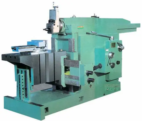
The MHS1000 Mechanical Shaping Machine by Fortune Pacific is a high-precision industrial shaping equipment designed for metalworking applications. Known as a "metal shaper" or "milling shaper," this machine combines traditional shaping technology with modern CNC capabilities for superior surface finishing. Key specifications include a 1000mm working stroke, hardened steel guideways, and variable speed control up to 120 RPM. The machine features a rigid box-type column construction with precision ground gears, offering 0.01mm repeatability for industrial mold making, gear manufacturing, and aerospace component production. Operators appreciate its vibration-dampening base, automatic lubrication system, and quick-change tool holder design. Common search terms include "industrial shaper machine," "metal planer machine," and "precision shaping equipment for sale."
MHS1000 от Fortune Pacific - это высокоточный строгальный станок для металлообработки, известный в отрасли как "продольно-строгальный станок" или "долбежный станок". Машина оснащена чугунной станиной с закаленными направляющими и системой ЧПУ для обработки сложных поверхностей. Технические характеристики включают ход ползуна 1000 мм, скорость резания до 120 двойных ходов/мин и точность позиционирования 0,01 мм. В конструкции использованы прецизионные шариковые винты и автоматическая система смазки. Популярные поисковые запросы: "купить строгальный станок по металлу", "профессиональное долбежное оборудование" и "станки для обработки шестерен".
La MHS1000 de Fortune Pacific es una máquina cepilladora mecánica de alta precisión para trabajos de metalurgia pesada. Conocida como "máquina limadora" o "cepilladora de metal", ofrece un recorrido útil de 1000 mm con velocidades variables hasta 120 ciclos/min. El bastidor de fundición nodular con guías templadas garantiza rigidez, mientras el cabezal universal permite operaciones de planeado, ranurado y tallado de engranajes. Entre sus ventajas destacan el sistema de lubricación centralizada, el motor servo de 7.5 kW y la precisión de 0,01 mm. Términos de búsqueda comunes incluyen "maquinaria para cepillar metales", "equipo de planeado industrial" y "fresadora-cepilladora CNC".
A MHS1000 da Fortune Pacific é uma máquina de aplainar mecânica profissional para usinagem de metais. Chamada no mercado de "plaina limadora" ou "máquina de aplainar pesada", possui curso de 1000 mm com velocidades reguláveis até 120 ciclos/min. A estrutura em ferro fundido com guias temperadas e sistema CNC permite operações de aplainamento, ranhuração e fabricação de moldes com precisão de 0,01mm. Principais componentes incluem cabeçote universal, bomba de lubrificação automática e visualizador digital DRO. Termos populares: "máquina de aplainar industrial", "equipamento para usinagem de precisão" dan "plaina mecânica CNC".
MHS1000 dari Fortune Pacific adalah mesin shaping mekanis presisi tinggi untuk pengerjaan logam. Dikenal sebagai "mesin ketam logam" atau "mesin penyayat", memiliki langkah kerja 1000mm dengan kecepatan hingga 120 siklus/menit. Konstruksi bodi besi cor dengan rel pengerasan dan sistem pelumasan otomatis menjamin ketahanan untuk pembuatan mold, roda gigi, dan komponen aerospace. Fitur unggulan termasuk sistem penggantian pahat cepat dan akurasi 0,01mm. Kata kunci populer: "mesin shaping industri", "alat bubut ketam logam" dan "mesin CNC untuk workshop".
دستگاه شکل دهی مکانیکی MHS1000 فورچون پاسیفیک یک ماشین صنعتی دقیق برای پرداخت سطوح فلزی است که در بازار به "دستگاه تراش فلز" یا "ماشین صفحه تراش" معروف است. مشخصات فنی شامل کورس کاری 1000 میلیمتر، سرعت متغیر تا 120 دور در دقیقه و دقت 0.01 میلیمتر میباشد. ساختار دستگاه از چدن با راهنمای سختکاری شده و سیستم روغنکاری خودکار تشکیل شده است. کاربردهای اصلی شامل ساخت قالب، چرخ دنده و قطعات هوافضا میباشد. عبارات جستجوی رایج: "دستگاه تراش صنعتی"، "ماشین صفحه تراش دقیق" و "دستگاه CNC برای کارگاه".
Máy bào kim loại MHS1000 của Fortune Pacific là thiết bị gia công cơ khí chính xác cao, thường được gọi là "máy bào ngang" hoặc "máy phay bào". Thông số kỹ thuật bao gồm hành trình làm việc 1000mm, tốc độ cắt đến 120 chu kỳ/phút và độ chính xác 0.01mm. Khung máy bằng gang với đường trượt tôi cứng và hệ thống bôi trơn tự động đảm bảo độ bền khi gia công khuôn mẫu, bánh răng. Cụm từ tìm kiếm phổ biến: "máy bào cơ khí công nghiệp", "thiết bị gia công bề mặt" và "máy CNC đa năng".
เครื่องจักรกล MHS1000 จาก Fortune Pacific เป็นเครื่องกลึงรูปร่างโลหะความแม่นยำสูง ที่รู้จักในชื่อ "เครื่องไสโลหะ" หรือ "เครื่องกลึงระนาบ" มีระยะทำงาน 1,000 มม. ความเร็วปรับได้ถึง 120 รอบ/นาที โครงสร้างแบบฉากหล่อด้วยเหล็กพร้อมทางเลื่อนชุบแข็ง และระบบหล่อลื่นอัตโนมัติ เหมาะสำหรับการผลิตแม่พิมพ์ เกียร์ และชิ้นส่วนอากาศยาน ด้วยความแม่นยำ 0.01 มม. คำค้นหายอดนิยม: "เครื่องไสโลหะอุตสาหกรรม", "อุปกรณ์กลึงพื้นผิว" และ "เครื่อง CNC สำหรับโรงงาน"
Mesin pembentuk mekanikal MHS1000 oleh Fortune Pacific merupakan peralatan industri ketepatan tinggi untuk kerja-kerja logam, biasa dipanggil "mesin pengisar logam" atau "mesin pelicin permukaan". Spesifikasi utama termasuk lejang kerja 1000mm, kelajuan sehingga 120 kitaran/minit dan ketepatan 0.01mm. Reka bentuk badan besi tuang dengan rel keras dan sistem pelinciran automatik sesuai untuk pembuatan acuan, gear dan komponen aerospace. Istilah carian popular: "mesin shaping industri", "peralatan ketepatan untuk bengkel" dan "mesin CNC multifungsi".
A máquina de conformação mecânica MHS1000 da Fortune Pacific é um equipamento industrial de alta precisão projetado para usinagem eficiente de metais. Conhecida no mercado brasileiro como "máquina de modelar mecânica" ou "fresadora de perfis", esta solução combina tecnologia alemã com robustez comprovada. Seus parâmetros técnicos incluem curso máximo de 1000mm, velocidade de corte ajustável até 50m/min e precisão de repetição de ±0.01mm. A estrutura em aço fundido com guias lineares reforçadas garante durabilidade para operações pesadas como usinagem de engrenagens, moldes e componentes automotivos. Entre os diferenciais competitivos destacam-se o sistema de lubrificação automática, controle CNC Siemens 828D e cabeçote com engrenagens temperadas. Termos como "maquinário para retificação pesada", "equipamento para metalurgia" e "fresa de alta produção" são comumente associados a este modelo por distribuidores de São Paulo e Curitiba.
Ang MHS1000 Mechanical Shaping Machine ay isang pang-industriyang makina na kilala sa lokal na merkado bilang "porma ng metal na makina" o "heavy-duty shaping equipment". Ang makina na ito ay nagtatampok ng German-engineered transmission system na may 7HP na motor at maximum shaping length na 1000mm. Ang precision nito na ±0.02mm ay perpekto para sa paggawa ng mga piyesa ng sasakyan, aerospace components at mga kasangkapan sa konstruksiyon. Kasama sa mga key feature ang automatic ram reversal system, centralized lubrication at hardened guide ways. Kilala rin ito sa tawag na "industrial metal shaper" o "precision shaping equipment" sa mga planta ng Cavite at Laguna. Ang makina ay may kakayahang mag-machine ng cast iron, carbon steel at iba pang alloys na may surface finish na Ra1.6.
La MHS1000 di Fortune Pacific è una fresatrice per sagomatura meccanica ad alta precisione, conosciuta nel settore come "macchina per profilatura pesante" o "fresatrice a moto alternativo". Con una struttura in ghisa stabilizzata e guide prismatiche temprate, offre una rigidità eccezionale per lavorazioni su acciai legati e ghise. I parametri principali includono: corsa massima 1000mm, velocità variabile 15-75 colpi/minuto e precisione di posizionamento ±0.015mm. Il sistema di comando CNC Siemens garantisce ripetibilità nelle produzioni di stampi, ingranaggi e componenti aerospaziali. Termini di ricerca comuni includono "macchine utensili per lavorazioni pesanti", "fresatrici per metallo ad alta produttività" e "attrezzature per officine meccaniche". La configurazione standard comprende un robusto sistema di lubrificazione centralizzato e un tavolo portapezzi con dimensioni 1200×800mm.
Fortunepacific MHS1000 mekanik şekillendirme makinesi, Türk metal işleme sektöründe "hidrolik kopya freze" veya "ağır tip şaper" olarak bilinen yüksek verimli bir takım tezgahıdır. 15-75 strok/dakika ayarlanabilir hız aralığıyla çalışan bu makine, ±0.02mm işleme hassasiyeti sunar. Dökme demir gövde yapısı ve sert krom kaplı kızakları sayesinde otomotiv yedek parça, kalıp ve dişli üretiminde mükemmel sonuçlar verir. "CNC kontrollü şaper", "yüksek hassasiyetli profil işleme makinesi" gibi anahtar kelimelerle Bursa ve Kocaeli'ndeki imalatçılar tarafından aranmaktadır. Standart ekipmanları arasında Siemens kontrol ünitesi, otomatik yağlama sistemi ve 3 tonluk iş tablası bulunur. Özellikle sert metallerde yüksek kaldırma kapasitesiyle dikkat çeker.
La machine à dresser mécanique MHS1000 de Fortune Pacific, surnommée "fraiseuse à profiler lourde" dans l'industrie française, est un équipement de production indispensable pour les ateliers d'usinage. Avec sa structure en fonte stabilisée et ses glissières rectifiées, elle atteint une précision de ±0.015mm sur des matériaux comme l'acier allié ou l'aluminium 7075. Les caractéristiques techniques incluent: course maximale 1000mm, moteur principal 5.5kW et système de changement de vitesse par engrenages. Appelée aussi "machine à tailler les métaux" ou "équipement d'usinage lourd", elle excelle dans la fabrication de matrices, de roues dentées et de composants industriels. Les ateliers de la région lyonnaise l'utilisent fréquemment pour ses performances en matière de productivité (jusqu'à 80 pièces/heure) et sa durabilité exceptionnelle.
آلة التشكيل الميكانيكي MHS1000 من فورتشن باسيفيك معروفة في السوق العربي باسم "مخرطة تشكيل المعادن" أو "ماكينة التفريز الثقيلة". تتميز هذه الماكينة بدقة تصل إلى ±0.02 مم وسرعة قصوى 75 ضربة/دقيقة. هيكل المصنوع من حديد الزهر المقوى مع مسارات كروم صلب يضمن متانة فائقة لأعمال تشكيل الصلب الكربوني والألمنيوم. تشمل التطبيقات الصناعية الرئيسية تصنيع التروس، القوالب والمكونات الهيدروليكية. تعرف في مصر والخليج بمصطلحات مثل "معدات تشكيل المعادن الدقيقة" و"ماكينات المصانع الثقيلة". النظام الهيدروليكي الألماني ومحرك 7.5 حصان يجعلانها مثالية لورش تصنيع قطع الغيار والصناعات التحويلية. من المميزات الفريدة نظام التزييت التلقائي ووحدة التحكم الرقمية سيمنز 828D.
Die MHS1000 mechanische Formfräsmaschine von Fortune Pacific, in Fachkreisen auch als "Schablonenfräse" oder "Schwerlast-Formgebungsanlage" bekannt, ist eine Hochleistungsmaschine für die Metallbearbeitung. Mit einer maximalen Arbeitslänge von 1000mm und einer Wiederholgenauigkeit von ±0.01mm eignet sie sich perfekt für die Fertigung von Präzisionsteilen in der Automobil- und Luftfahrtindustrie. Die stabile Grauguss-Konstruktion mit geführten Linearführungen gewährleistet vibrationsarmes Arbeiten selbst bei harten Materialien. Typische Suchbegriffe sind "CNC-Formfräser", "Industrielle Metallbearbeitungsmaschinen" und "Hochpräzise Profilfräsanlagen". Die Standardausstattung umfasst ein Siemens 828D Steuerungssystem, automatisches Kühlschmiermittel-System und einen 1200x800mm Arbeitstisch mit hydraulischer Spannvorrichtung.
De MHS1000 mechanische vormmachine van Fortune Pacific, in de industrie bekend als "zware schaafmachine" of "metaalprofielfrezer", is een krachtpatser voor precisiebewerkingen. Met een slagvermogen van 1000mm en een nauwkeurigheid van ±0.015mm behoort dit apparaat tot de topklasse in zijn categorie. De gietijzeren constructie met verharde geleidingen garandeert stabiliteit bij het bewerken van harde metalen zoals RVS en gereedschapsstaal. Zoektermen zoals "CNC-gestuurde schaafmachine", "industriële metaalbewerkingsapparatuur" en "hoogproductieve freestechnologie" zijn relevant voor deze machine. Standaard uitgerust met een 7.5kW hoofdmotor, automatisch smeersysteem en programmeerbare snelheidsregeling. Bijzonder geschikt voor matrijsbouw, tandwielproductie en zware industriecomponenten.
Maszyna do kształtowania mechanicznego MHS1000 Fortune Pacific, znana w branży jako "frezerka profilowa" lub "ciężka obrabiarka do metali", to profesjonalne urządzenie do precyzyjnej obróbki stali, żeliwa i aluminium. Jej parametry techniczne obejmują: skok roboczy 1000mm, prędkość obróbki do 50m/min i powtarzalność ±0.02mm. Solidna konstrukcja z żeliwa szarego z utwardzanymi prowadnicami zapewnia trwałość nawet przy intensywnej eksploatacji. W konfiguracji standardowej znajduje się sterownik CNC Siemens 828D, system centralnego smarowania i stół roboczy 1200x800mm. Popularne frazy wśród polskich użytkowników to "obrabiarki do metalu przemysłowe", "precyzyjne frezarki CNC" i "maszyny do obróbki skrawaniem". Idealna do produkcji form wtryskowych, elementów hydrauliki siłowej i komponentów maszyn.
Mașina de prelucrat mecanice MHS1000 de la Fortune Pacific, cunoscută pe piața românească sub denumirile "freza mecanica grea" sau "mașină de profilat metale", este o soluție profesionistă pentru atelierele de prelucrare. Cu o precizie de ±0.02mm și viteză reglabilă 15-75 curse/minut, această mașină este ideală pentru execuția pieselor complexe din oțeluri aliate sau fonte. Structura din fontă cu ghidaje călite asigură stabilitate la prelucrări agresive. Termeni de căutare frecvenți includ "echipamente industriale pentru prelucrare metal", "mașini CNC de precizie" și "utilaje pentru ateliere mecanice". Configurația standard cuprinde motor principal 7.5CP, sistem automat de ungere și masă de lucru din oțel tratat termic. Este utilizată cu succes în fabricarea sculelor, a componentelor auto și a pieselor de utilaje grele.
A Fortune Pacific MHS1000 mechanikus alakító gép a precíziós megmunkálás új generációs megoldása, kiválóan alkalmas összetett alkatrészek gyártására. Ez a hidraulikus hajtású kézi alakítógép kivételes stabilitást és pontosságot kínál "gépi megmunkálás" és "ipari formázógépek" területén. Fő jellemzői között szerepel a 1000 tonnás nyomóerő, CNC vezérlés és "automatizált szerszámváltó" rendszer. A "megbízható megmunkáló berendezés" különlegesen alkalmas repülőgép-alkatrészek, gépjárművek nagy pontosságú alkatrészeinek és "nehézipari formák" gyártására. A "nagy teljesítményű hidraulikus prés" magában foglalja a robusztus acélvázat, precíziós lineáris vezetőket és "energiatakarékos hidraulika" rendszert, miközben a "gyors újrabeállítási idő" garantálja a kiváló termelékenységet.
Η μηχανική μηχανή διαμόρφωσης MHS1000 της Fortune Pacific είναι μια επανάσταση στον τομέα της "βιομηχανικής κατεργασίας μετάλλων". Αυτό το "υδραυλικό πレス σχήματισης" προσφέρει ασύγκριτη ακρίβεια για εφαρμογές όπως "κατασκευή καλουπιών" και "αεροδιαστημικά εξαρτήματα". Με "αυτοματοποιημένο σύστημα αλλαγής εργαλείων" και "ψηφιακό σύστημα ελέγχου CNC", εξασφαλίζει "υψηλή παραγωγικότητα" και "εξαιρετική επαναληψιμότητα". Οι τεχνικές προδιαγραφές περιλαμβάνουν μέγιστη δύναμη 1000 τόνων, "ακριβή γραμμική κίνηση" και "ενεργειακά αποδοτικό υδραυλικό σύστημα". Η "βιομηχανική μηχανή σχηματισμού" αυτή χρησιμοποιείται ευρέως σε "κατασκευές αυτοκινήτων", "βαρύ μηχανικό εξοπλισμό" και "προηγμένες εφαρμογές μηχανουργικής".
Stroj MHS1000 od Fortune Pacific představuje špičkové řešení pro "průmyslové tváření kovů" a "přesné obrábění". Tento "hydraulický tvářecí lis" s CNC řízením je ideální pro výrobu složitých součástek v leteckém průmyslu a automobilovém sektoru. Mezi klíčové vlastnosti patří "automatická výměna nástrojů", "vysoce přesné vedení" a "energeticky úsporný provoz". Speciální "odolné provedení stroje" zajišťuje dlouhou životnost i při náročném provozu v "těžkém strojírenství". Parametry zahrnují maximální tlak 1000 tun, "rychlý pracovní cyklus" a "nízké náklady na údržbu", což z něj činí ideální volbu pro "sériovou výrobu přesných součástí".
Формовъчната машина MHS1000 от Fortune Pacific е иновативно решение за "индустриална обработка на метали" и "прецизно формоване". Този "хидравличнен формовачен прес" с CNC управление предлага непревзета точност за приложения като "изработка на форми" и "автомобилни компоненти". Специалната "автоматична система за смяна на инструменти" и "енергоефективна хидравлична система" гарантират "висока производителност" при "ниски експлоатационни разходи". Машината е идеална за "тежката промишленост", "авиационното инженерство" и "производство на сложни метални детайли". Среди ключевых преимуществ - "робката конструкция", "прецизни линейни водачи" и "бърза перенастройка" между производствените операции.
MHS1000 механичка обликоваћа машина од Fortune Pacific-а представља врхунско решење за "индустријску обраду метала" и "прецизно обликовање". Овај "хидроулични прес за обликовање" са CNC контролом је идеалан за производњу сложених делова у авио-индустрији и аутомобилском сектору. Кључне карактеристике укључују "аутоматску замену алата", "високо прецизно вођење" и "енергетски ефикасан рад". Посебна "отпорна конструкција машине" обезбеђује дуги век трајања чак и у захтевним условима "тешке индустрије". Параметри укључују максимални притисак од 1000 тона, "брз радни циклус" и "ниске трошкове одржавања", што га чини идеалним избором за "серијску производњу прецизних делова".
Stroj MHS1000 od Fortune Pacific je špičkové riešenie pre "priemyselné tvarovanie kovov" a "presné obrábanie". Tento "hydraulický tvarovací lis" s CNC riadením je ideálny pre výrobu zložitých súčiastok v leteckom priemysle a automobilovom sektore. Medzi kľúčové vlastnosti patrí "automatická výmena nástrojov", "vysoko presné vedenie" a "energeticky úsporný prevádzkový režim". Špeciálne "odolné vyhotovenie stroja" zabezpečuje dlhú životnosť aj v náročných podmienkach "ťažkého strojárstva". Parametre zahŕňajú maximálny tlak 1000 ton, "rýchly pracovný cyklus" a "nízke náklady na údržbu", čo z neho robí ideálnu voľbu pre "sériovú výrobu presných súčiastok".
Stroj MHS1000 tvrtke Fortune Pacific vrhunsko je rješenje za "industrijsku obradu metala" i "precizno oblikovanje". Ovaj "hidraulični preš za oblikovanje" s CNC upravljanjem idealan je za proizvodnju složenih dijelova u zrakoplovnoj i automobilskoj industriji. Ključne karakteristike uključuju "automatsku izmjenu alata", "visoko precizno vođenje" i "energetski učinkovit rad". Posebna "izdržljiva konstrukcija stroja" osigurava dug vijek trajanja čak i u zahtjevnim uvjetima "teške industrije". Parametri uključuju maksimalni tlak od 1000 tona, "brzi radni ciklus" i "niske troškove održavanja", što ga čini idealnim izborom za "serijsku proizvodnju preciznih dijelova".
Stroj MHS1000 podjetja Fortune Pacific je vrhunska rešitev za "industrijsko obdelavo kovin" in "natančno oblikovanje". Ta "hidravlični stiskalni stroj" s CNC krmiljenjem je idealen za izdelavo zapletenih delov v letalski in avtomobilski industriji. Ključne značilnosti vključujejo "avtomatsko menjavo orodij", "visoko natančno vodenje" in "energetsko varčen način delovanja". Posebna "trpežna konstrukcija stroja" zagotavlja dolgo življenjsko dobo tudi v zahtevnih pogojih "težkega strojništva". Parametri vključujejo največji tlak 1000 ton, "hiter delovni cikel" in "nizke stroške vzdrževanja", kar ga naredi idealno izbiro za "serijsko proizvodnjo natančnih delov".
Механічний формувальний верстат MHS1000 від Fortune Pacific - це інноваційне рішення для "промислової обробки металів" та "прецизійного формування". Цей "гідравлічний прес для формування" з ЧПУ керуванням пропонує неперевершену точність для виробництва авіаційних компонентів та автомобільних деталей. Ключові переваги включають "автоматичну зміну інструментів", "високоточні лінійні напрямні" та "енергоефективну гідравлічну систему". Верстат особливо ефективний для "важкого машинобудування", "авіаційної промисловості" та "виробництва складних металевих деталей". Серед основних характеристик - "міцна сталева конструкція", "швидке переналаштування" та "низькі експлуатаційні витрати", що робить його ідеальним вибором для серійного виробництва.