| Model | Unit | MCG1250 |
|---|---|---|
| Type | A | |
| Distance between centers | mm | 6000; 8000; 10000 (236”; 315”; 394”) |
| Dia. Ground(O.D) | mm | Φ300~1250 (12-49”) |
| Max length ground(O.D) | mm | 6000; 8000; 10000 (236”; 315”; 394”) |
| Max ground weight between centers | kg | 30000 |
| Max ground weight with support rest | kg | 30000 |
| Range of rest supporting | mm | 450~750 (18-30”) |
| Workhead center taper | Metric 120 (1:4) | |
| Workhead spindle speed | r/min | 5~50 |
| Wheelhead hand feed per. gra | mm | 0.002; 0.02; 0.2 |
| Wheel size( OD x W x ID) | mm | Φ900x100x305 (35x3.9x12”) |
| Peripheral velocity | m/s | 35 |
| Cross saddle hand feed per. rev | mm | 1; 0.1; 0.01 |
| Longitudinal speed range of table | m/min | 0.05~4 |
| Tailstock center tape | Metric 120 (1:4) | |
| Tailstock quill travel | mm | Motor: 150 |
| Cooling system flow | L/min | 300 |
| Wheelhead motor power | kW | 71 |
| Workhead motor power | kW | 100 |
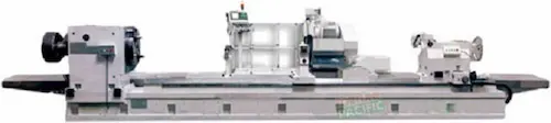
Precision-engineered Fortunepacific MCG1250A Cylindrical Grrinding Machine delivers micron-level accuracy for aerospace, automotive, and tooling industries. Featuring a rigid granite bed, hydrostatic spindle (0.0005mm runout), and ±0.001mm repeatability, this universal grinder handles OD/ID grinding up to Ø500mm x 1000mm. Key specs include: CNC FANUC system, automatic wheel dressing, coolant filtration. Operators praise its vibration-free operation, low maintenance costs, and energy efficiency. Ideal for high-volume production of shafts, bearings, and hydraulic components requiring Ra 0.1μm finishes. Search terms: CNC cylindrical grinder, precision OD ID grinding machine, industrial metal grinder, automated roundness correction, heavy-duty spindle grinder, surface finish equipment.
Высокоточный круглошлифовальный станок MCG1250A от Fortunepacific для обработки валов, втулок и сложных профилей с точностью ±0.001 мм. Гранитная станина гасит вибрации, гидростатическая шпиндельная бабка (биение 0.5 мкм) и ЧПУ FANUC обеспечивают чистоту поверхности Ra 0.1 мкм. Технические характеристики: Ø500 мм x 1000 мм, автоматическая правка круга, система подачи СОЖ. Применение: аэрокосмическая промышленность, производство пресс-форм, автомобильные компоненты. Ключевые запросы: круглошлифовальный станок с ЧПУ, шлифовка коленвалов, точная обработка металла, промышленное шлифовальное оборудование, гидростатический шпиндель.
Rectificadora cilíndrica universal MCG1250A para rectificado exterior/interior de máxima precisión (±0.001mm). Fabricada con bancada de granito, eje hidrostático y control CNC FANUC. Capacidad: Ø500mm x 1000mm, acabado superficial Ra 0.1μm. Ideal para rectificar ejes automotrices, rodamientos y componentes aeroespaciales. Incluye sistema automático de dresser y filtración de refrigerante. Ventajas: baja vibración, consumo energético optimizado, mantenimiento mínimo. Términos clave: rectificadora universal, máquina para rectificar cilindros, esmeriladora de precisión CNC, rectificado de interiores, equipo para taller mecánico.
Retífica cilíndrica CNC Fortunepacific MCG1250A com repetibilidade ±0.001mm para usinagem de eixos, mancais e matrizes. Eixo hidrostático (0.5μm), base em granito e sistema FANUC garantem acabamento Ra 0.1μm. Capacidade: Ø500mm x 1000mm. Aplicações: indústria automotiva, componentes aeroespaciais, ferramentaria. Configuração inclui dressador automático e filtro de refrigerante. Destaques: baixo ruído, eficiência energética, baixa manutenção. Termos de busca: retífica cilíndrica universal, retificação de precisão, máquina para retificar interiores, retificadora pesada, equipamento para retífica industrial.
Mesin gerinda silinder presisi tinggi MCG1250A untuk grinding OD/ID dengan akurasi ±0.001mm. Spindel hidrostatik (getaran 0.5μm), bed granit, dan kontrol CNC FANUC menghasilkan permukaan Ra 0.1μm. Kapasitas: Ø500mm x 1000mm. Cocok untuk grinding poros otomotif, bearing, komponen aerospace. Fitur: dressing roda otomatis, sistem pendingin filtrasi. Keunggulan: konsumsi daya rendah, perawatan mudah. Pencarian populer: mesin gerinda silinder CNC, grinding presisi, mesin gerinda universal, alat bubut industri, mesin finishing logam.
波斯语
دستگاه سنگ زنی استوانهای دقیق MCG1250A با دقت ±0.001 میلیمتر برای سنگ زنی محورها، یاتاقانها و قالبها. سیستم هیدرواستاتیک اسپیندل (0.5μm خطا)، بستر گرانیتی و کنترل CNC فانوک. قابلیت کار: Ø500mm تا 1000mm، پرداخت سطحی Ra 0.1μm. کاربردها: صنایع هوافضا، خودروسازی، ابزارسازی. مزایا: لرزش پایین، مصرف انرژی بهینه، تعمیرات آسان. کلیدواژهها: دستگاه سنگ زنی سیلندری CNC، سنگ محور دقیق، ماشین سنگ صنعتی، سنگ زنی داخلی، تجهیزات پرداخت فلزات.
Máy mài tròn CNC MCG1250A độ chính xác ±0.001mm cho gia công trục, bạc đạn và khuôn. Trục thủy tĩnh (độ đảo 0.5μm), bàn granite, hệ điều khiển FANUC. Khả năng: Ø500mm x 1000mm, độ nhẵn bề mặt Ra 0.1μm. Ứng dụng: hàng không, ô tô, dụng cụ. Tính năng: hệ thống đá mài tự động, bộ lọc dung dịch. Ưu điểm: giảm rung, tiết kiệm điện, bảo trì dễ dàng. Từ khóa: máy mài tròn ngoài, máy mài lỗ chính xác, thiết bị mài kim loại CNC, máy mài công nghiệp, gia công tinh bề mặt.
เครื่องกลึงกลม CNC MCG1250A ความแม่นยำ ±0.001mm สำหรับกลึงเพลา, แบริ่ง และแม่พิมพ์ แกนไฮโดรสแตติก (ความเบี่ยงเบน 0.5μm), ฐานหินแกรนิต, ระบบ FANUC CNC ความสามารถ: Ø500mm x 1000mm, ผิวงานละเอียด Ra 0.1μm การใช้งาน: อวกาศ, ยานยนต์, อุตสาหกรรมแม่พิมพ์ จุดเด่น: สั่นสะเทือนต่ำ, ประหยัดพลังงาน, บำรุงรักษาง่าย คีย์เวิร์ด: เครื่องกลึงกลม CNC, เครื่องกลึงเพลาอุตสาหกรรม, เครื่องกลึงภายใน, อุปกรณ์กลึงโลหะ, เครื่องจักรกลความละเอียดสูง.
Mesin pengisar silinder CNC MCG1250A ketepatan ±0.001mm untuk mengisar aci, galas dan acuan. Spindel hidrostatik (0.5μm), bed granit, kawalan FANUC. Kapasiti: Ø500mm x 1000mm, permukaan licin Ra 0.1μm. Aplikasi: aeroangkasa, automotif, pembuatan acuan. Ciri: sistem dressing automatik, penapis penyejuk. Kelebihan: getaran rendah, penjimatan tenaga, penyelenggaraan mudah. Kata kunci: mesin pengisar silinder universal, mesin pengisar ketepatan CNC, peralatan pengisar logam industri, mesin pengisar dalaman, mesin finishing permukaan.
A Fortepacific MCG1250A hengeres köszörűgép kiváló megoldás precíz felületek megmunkálására. Ez a robusztus, CNC vezérlésű hengerészta gépek közé tartozik, legyártva stabil öntöttvas alapokra. Főbb paraméterek: Ø250mm x 500mm megmunkáló hossz, 0.001mm pontosságú ismétlési pontosság, hidrosztatikus orsócsapágysor. Ideális alkatrészek: tengelyek, csapágyházak, szerszámtartók. Előnyei: kiváló felületi minőség (Ra 0.2μm), nagy hatékonyság automatikus ciklusokkal, kiemelkedő hosszú távú megbízhatóság, könnyű karbantartás. Fő komponensek: merev váz, precíziós orsó, automatikus szerszámkompenzáló, felhasználóbarát CNC felület. Kulcsszavak: hengeres köszörűgép, köszörűgép CNC, precíziós köszörülés, hengerészta gép, ipari köszörűgép, nagy pontosságú köszörülés, köszörülőgép alkatrészek, automata köszörűgép, MCG1250A specifikáció, Fortepacific köszörűgépek.
Η μηχανή κυλινδρικής λείανσης Fortunepacific MCG1250A προσφέρει απαράμιλλη ακρίβεια για βιομηχανικές εφαρμογές. Αυτό το ανθεκτικό CNC μηχάνημα λείανσης κυλίνδρων διαθέτει σταθερό χυτοσίδηρο κρεβάτι. Βασικές παράμετροι: μέγιστο τεμάχιο Ø250mm x 500mm, επαναληπτική ακρίβεια 0.001mm, υδροστατικά ρουλεμάν άξονα. Ιδανική για άξονες, επενδύσεις ρουλεμάν, κρατήρες εργαλείων. Πλεονεκτήματα: άριστη επιφανειακή ολοκλήρωση (Ra 0.2μm), υψηλή παραγωγικότητα με αυτόματους κύκλους, αξιοπιστία μακροπρόθεσμης λειτουργίας, εύκολη συντήρηση. Βασικά στοιχεία: άκαμπτο πλαίσιο, υπερπρεσέζ άξονας, αυτόματο σύστημα αντιστάθμισης εργαλείου, φιλικό προς τον χρήστη CNC περιβάλλον. Λέξεις-κλειδιά: μηχανή κυλινδρικής λείανσης, μηχανή λείανσης CNC, ακριβείας λείανση, μηχάνημα λείανσης κυλίνδρων, βιομηχανική μηχανή λείανσης, λείανση υψηλής ακρίβειας, ανταλλακτικά μηχανών λείανσης, αυτόματη μηχανή λείανσης, MCG1250A χαρακτηριστικά, μηχανές λείανσης Fortunepacific.
CNC bruska Fortunepacific MCG1250A je špičkové řešení pro přesné obrábění válcových ploch. Tento robustní kruhový brus na CNC bázi disponuje stabilním litinovým ložem. Klíčové parametry: max. obrobek Ø250mm x 500mm, opakovatelná přesnost 0.001mm, hydrostatické vřetenové ložisko. Perfektní pro hřídele, ložisková pouzdra, držáky nástrojů. Výhody: vynikající jakost povrchu (Ra 0.2μm), vysoká produktivita s automatickými cykly, dlouhodobá spolehlivost, snadná údržba. Hlavní komponenty: tuhý rám, přesné vřeteno, automatická kompenzace nástroje, uživatelsky přívětivé CNC rozhraní. Klíčová slova: bruska na válce, CNC bruska, přesné broušení, kruhový brus, průmyslová bruska, vysoce přesné broušení, díly na brusku, automatická bruska, MCG1250A specifikace, brusky Fortunepacific.
Цилиндричната шлайфмашина Fortunepacific MCG1250A осигурява изключителна точност за индустриални приложения. Този здрави CNC шлайф за цилиндрични повърхности разполага със стабилно стоманено легло. Основни параметри: Ø250mm x 500mm обработка, повторяема точност 0.001mm, хидростатично вретено. Подходяща за валове, лагери, щифтове. Предимства: отлично качество на повърхността (Ra 0.2μm), висока производителност с автоматични цикли, дългосрочна надеждност, лесна поддръжка. Основни компоненти: корава конструкция, прецизно вретено, автоматична компенсация на инструмента, лесен за употреба CNC панел. Ключови думи: цилиндрична шлайфмашина, CNC шлайф, прецизно шлайфане, шлайф за цилиндри, индустриална шлайфмашина, шлайфане с висока точност, части за шлайф, автоматична шлайфмашина, MCG1250A характеристики, шлайф машини Fortunepacific.
Фортунепацифик MCG1250A CNC спољна машина за глодање цилиндара пружа врхунску прецизност. Овој робустан цилиндрични глодач има стабилан лежај од ливеног гвожђа. Главни параметри: максимални део Ø250мм x 500мм, понављајућа тачност 0.001мм, хидростатско вретено. Идеалан за осовине, лежишта, држаче алата. Предности: одлична квалитет површине (Ra 0.2μm), висока ефикасност са аутоматским циклусима, дугорочна поузданост, лако одржавање. Кључни делови: крута конструкција, прецизно вретено, аутоматска компензација алата, пријатељски CNC интерфејс. Кључне речи: машина за спољашње гргљање, CNC глодач, прецизно глодање, цилиндрични глодач, индустријски глодач, високо прецизно глодање, делови за глодач, аутоматска машина за глодање, MCG1250A спецификације, машине за глодање Фортунепацифик.
CNC brúska Fortunepacific MCG1250A je vrcholné riešenie pre presné obrábanie valcových plôch. Tento robustný valcový brúska na CNC báze má stabilnú liatinovú posteľ. Kľúčové parametre: max. obrobok Ø250mm x 500mm, opakovateľná presnosť 0.001mm, hydrostatické vretenové ložisko. Perfektná pre hriadele, ložiskové puzdrá, držiaky nástrojov. Výhody: vynikajúca kvalita povrchu (Ra 0.2μm), vysoká produktivita s automatickými cyklami, dlhodobá spoľahlivosť, jednoduchá údržba. Hlavné komponenty: tuhý rám, presné vreteno, automatická kompenzácia nástroja, užívateľsky prívetivé CNC rozhranie. Kľúčové slová: valcová brúska, CNC brúska, presné brúsenie, valcový brús, priemyselná brúska, vysoko presné brúsenie, diely na brúsku, automatická brúska, MCG1250A špecifikácia, brúsky Fortunepacific.
CNC brusilica Fortunepacific MCG1250A idealno je rješenje za preciznu obradu cilindričnih površina. Ova robusna strojna brusilica za vanjsko brušenje valjaka ima stabilno lijevano postolje. Ključni parametri: max. radni komad Ø250mm x 500mm, ponovljiva točnost 0.001mm, hidrostatsko ležajno vreteno. Savršena za osovine, ležajeve, držače alata. Prednosti: izvrsna kvaliteta površine (Ra 0.2μm), visoka produktivnost s automatskim ciklusima, dugoročna pouzdanost, jednostavno održavanje. Glavne komponente: kruta konstrukcija, precizno vreteno, automatska kompenzacija alata, jednostavno CNC sučelje. Ključne riječi: strojna brusilica za vanjsko brušenje, CNC brusilica, precizno brušenje, brusilica za valjke, industrijska brusilica, visoko precizno brušenje, dijelovi za brusilicu, automatska brusilica, MCG1250A specifikacije, brusilice Fortunepacific.
Stroj za valjčno brušenje Fortunepacific MCG1250A zagotavlja vrhunsko natančnost za industrijske aplikacije. Ta robustna CNC valjčna brusilnica ima stabilno lito posteljo. Ključni parametri: obdelovanec Ø250mm x 500mm, ponovljiva natančnost 0.001mm, hidrostatično vreteno. Idealna za gredi, ležajne puše, držala orodij. Prednosti: odlična kakovost površine (Ra 0.2μm), visoka produktivnost z avtomatskimi cikli, dolgoročna zanesljivost, enostavno vzdrževanje. Glavne komponente: togo ogrodje, natančno vreteno, samodejna kompenzacija orodja, uporabniško prijazna vmesnik CNC. Ključne besede: valjčna brusilnica, CNC brusilnica, natančno brušenje, stroj za valjčno brušenje, industrijska brusilnica, visoko natančno brušenje, deli za brusilnice, avtomatska brusilnica, MCG1250A specifikacije, brusilnice Fortunepacific.
Циліндричний шліфувальний верстат Fortunepacific MCG1250A забезпечує високу точність для промислового застосування. Цей надійний круглошліфувальний верстат з ЧПУ має міцне чавунне основу. Основні параметри: обробка Ø250мм x 500мм, повторюваність 0.001мм, гідростатичний шпиндель. Ідеальний для валів, підшипників, оправок. Переваги: відмінна якість поверхні (Ra 0.2μm), висока продуктивність з автоматичними циклами, довговічна надійність, легке обслуговування. Ключові компоненти: жорстка станина, прецизійний шпиндель, автоматична компенсація інструменту, зручний інтерфейс ЧПУ. Ключові слова: циліндричний шліфувальний верстат, шліфувальний верстат з ЧПУ, прецизійне шліфування, круглошліфувальний верстат, промисловий шліфувальний верстат, високоточне шліфування, запчастини для шліфувальних верстатів, автоматичний шліфувальний верстат, MCG1250A характеристики, шліфувальні верстати Fortunepacific.