| Model | Unit | MCG1000 |
|---|---|---|
| Type | A | |
| Distance between centers | mm | 6000; 8000; 10000 (236”; 315”; 394”) |
| Dia. Ground(O.D) | mm | Φ240~1000 (9.4-39”) |
| Max length ground(O.D) | mm | 6000; 8000; 10000 (236”; 315”; 394”) |
| Max ground weight between centers | kg | 20000 |
| Max ground weight with support rest | kg | 20000 |
| Range of rest supporting | mm | 450~650 (18-26”) |
| Workhead center taper | Metric 120 (1:4) | |
| Workhead spindle speed | r/min | 5~50 |
| Wheelhead hand feed per. gra | mm | 0.002; 0.02; 0.2 |
| Wheel size( OD x W x ID) | mm | Φ900x100x305 (35x3.9x12”) |
| Peripheral velocity | m/s | 35 |
| Cross saddle hand feed per. rev | mm | 1; 0.1; 0.01 |
| Longitudinal speed range of table | m/min | 0.05~4 |
| Tailstock center tape | Metric 120 (1:4) | |
| Tailstock quill travel | mm | Motor: 150 |
| Cooling system flow | L/min | 200 |
| Wheelhead motor power | kW | 55 |
| Workhead motor power | kW | 55 |
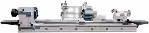
Fortunepacific MCG1000A hengeres köszörűgép kiváló választás precíziós felületek megmunkálásához. Ez a CNC hengermegmunkáló gép (hengeres köszörülő gépek) kivételes pontosságot és megbízhatóságot kínál nehézipari alkatrészek, automotív alkatrészek (autóipari alkatrészek köszörülése) és szerszámgyártás számára. Fő jellemzői: nagy fordulatszámú főorsó, robusztus öntvényváz, fejlett hidraulikus előtolásrendszer és automata mérőrendszer (automatikus mérés gépen). Kulcsfontosságú paraméterek: max. 1000mm megmunkálási hossz, 350mm köszörülendő átmérő, 0.001mm-es pontosságú követés. Nagy teljesítményű főmotor, precíziós lineáris vezető sín és tartós köszörűkövek (abrazív kövek) biztosítják a kiváló felületi minőséget és hosszú élettartamot. Ideális megoldás tömeggyártáshoz és egyedi, nagy pontosságú megmunkálásokhoz.
Η μηχανή κυλινδρικής λείανσης Fortunepacific MCG1000A είναι μια κορυφαία λύση CNC για απαιτητικές εφαρμογές. Αυτή η αυτόματη μηχανή λείανσης (ακριβείας) προσφέρει αξιοπιστία και υψηλή παραγωγικότητα στην επεξεργασία αξονικών έδρανων, μύλων, υδραυλικών εξαρτημάτων (εξαρτήματα υδραυλικών) και εργαλείων. Βασικά χαρακτηριστικά: άκαμπτο χάλυβα χύτευσης, ισχυρό υδραυλικό σύστημα τροφοδοσίας, αυτόματο σύστημα μέτρησης και αισθητήρας αντιστάθμισης τριβής. Παράμετροι: μέγιστο μήκος λείανσης 1000mm, μέγιστη διάμετρος 350mm, ακρίβεια θέσης 0.001mm. Ο βραχυκυκλωτής κινητήρας (ασύγχρονος κινητήρας), τα ακριβή γραμμικά ρουλεμάν οδήγησης και ο ισχυρός ηλεκτρικός έλεγχος εξασφαλίζουν εξαιρετική ομαλότητα επιφάνειας και σταθερότητα σε συνεχή λειτουργία. Ιδανική για βιομηχανίες αυτοκινήτων, αεροδιαστημικής και κατασκευής καλουπιών (καλούπια λείανση).
Fortunepacific MCG1000A je špičková CNC bruska na válcové plochy, určená pro náročné operace. Tento vysoce přesný válcový brus (brusky na válec) exceluje ve výrobě ložiskových krků, hřídelí, hydraulických komponentů a nástrojů. Klíčové vlastnosti: robustní litinový rám, výkonný hlavní vřeteno, pokročilý hydraulický posuv, automatický měřicí systém (automatické měření na brusce) a systém vyvažování brusných kotoučů. Parametry: max. délka broušení 1000mm, max. průměr broušení 350mm, přesnost 0.001mm. Výkonný hlavní motor, přesné lineární vedení a systém řízení posuvu zajišťují vynikající jakost povrchu a dlouhou životnost nástroje. Perfektní volba pro sériovou výrobu (hromadná výroba) a opracování tvrdých materiálů. Vyhledávejte: CNC brusky, válcové broušení, průmyslové brusky.
Фортунепасифик MCG1000A е високоточна цилиндрична шлайфмашина с ЧПУ за прецизно шлайфане на валове, оси, лагери и хидравлични компоненти. Този здравинен шлайф (шлайфане на цилиндри) се отличава с изключителна точност и надеждност за тежката индустрия и автомобилния сектор. Основни характеристики: масивна чугунена конструкция, високоскоростна шпиндела, хидравлична система за подаване, автоматична измерителна система (автоматично измерване на машината) и система за балансиране на шлайфовъчните камъни. Параметри: макс. дължина на шлайфане 1000мм, макс. диаметър 350мм, точност до 0.001мм. Мощният двигател, прецизните линейни водачи и стабилната управляваща система гарантират отлично качество на повърхността и висока производителност. Подходяща за масово производство и единични високоточни детайли. Търсете: CNC шлайфовъчни машини, цилиндрично шлайфане, промишлени шлайфачи.
Fortunepacific MCG1000A је прецизна CNC цилиндрична брусилица за обраду вратила, лежишта, хидрауличних компоненти и алата. Овај поуздани цилиндрац (цилиндричне брусилице) нуди изуздану тачност за аутомобилску индустрију и тешку механизацију. Карактеристике: чврста ливена конструкција, високобрзинско главно вратило, хидро систем за довод, аутоматски мерни систем (аутоматско мерење на машини) и систем за балансирање брусећих точка. Параметри: макс. дужина брушења 1000мм, макс. пречник 350мм, тачност од 0.001мм. Моћни главни мотор, прецизни линеарни водичи и напредна контрола осигуравају одликан квалитет површине и дуг век трајања алата. Идеална за серијску производњу (масовна производња) и обраду тврдих материјала. Претрага: CNC брусилице, цилиндрично брушење, индустријске брусилице.
Stroj Fortunepacific MCG1000A je vysoko výkonné CNC valcové brúske pre presné brúsenie hriadeľov, čapov, ložísk a hydraulických komponentov. Táto spoľahlivá valcovka (valcové brúsky) ponúka vynikajúcu presnosť pre automobilový priemysel a ťažké obrábanie. Parametre: max. dĺžka brúsenia 1000mm, max. priemer brúsenia 350mm, presnosť 0.001mm. Kľúčové vlastnosti: robustná liatinová konštrukcia, vysokootáčkové vreteno, hydraulický posuv, automatický merací systém (automatické meranie na stroji) a systém vyvažovania brúsnych kolies. Výkonný hlavný motor, presné lineárne vedenie a systém riadenia zabezpečujú vynikajúcu kvalitu povrchu a vysokú produktivitu. Ideálne pre sériovú výrobu a opracovanie tvrdých materiálov. Vyhľadávajte: CNC brúsky, valcové brúsenie, priemyselné brúsky.
Fortunepacific MCG1000A je vrhunska CNC cilindrična brusilica za precizno brušenje osovina, ležajeva, hidrauličkih komponenti i alata. Ova pouzdana brusilica za valjke (cilindrično brušenje) nudi iznimnu točnost za automobilsku industriju i alat. Ključne značajke: čvrsta lijevana konstrukcija, brzoglavno vreteno, hidraulični sustav za dovodenje, automatski mjerni sustav (automatsko mjerenje na stroju) i sustav za balansiranje brusnih kamenova. Parametri: max. duljina brušenja 1000mm, max. promjer 350mm, točnost od 0.001mm. Snažni glavni motor, precizni linearni vodilici i napredna kontrola osiguravaju izvrsnu kvalitetu površine i visoku produktivnost. Idealna za serijsku proizvodnju (masovna proizvodnja) i obradu tvrdih materijala. Pretražujte: CNC brusilice, cilindrično brušenje, industrijske brusilice.
Stroj Fortunepacific MCG1000A je visoko natančna CNC valjna brusilnik za obdelavo gredi, ležajev, hidravličnih komponentov in orodja. Ta zanesljiva valjna brusilnica (valjno brušenje) ponuja izjemno natančnost za avtomobilsko industrijo in obdelavo trdih materialov. Ključne lastnosti: robustna lita konstrukcija, visokohitrostna vretena, hidravlični sistem za podajanje, avtomatski merilni sistem (avtomatsko merjenje na stroju) in sistem za uravnoteženje brusnih koles. Parametri: max. dolžina brušenja 1000mm, max. premer 350mm, natančnost 0.001mm. Zmogljiv glavni motor, natančni linearni vodili in sistem vodenja zagotavljajo odlično kakovost površine in visoko zanesljivost. Idealna za serijsko proizvodnjo (masovno proizvodnjo) in specializirane natančne naloge. Iščite: CNC brusilniki, valjno brušenje, industrijski brusilniki.
Верстат Fortunepacific MCG1000A - це високоточний круглошліфувальний верстат з ЧПУ для обробки валів, шийок, підшипників та гідрокомпонентів. Цей надійний круглошліфувальний верстат (циліндричне шліфування) забезпечує високу точність для автомобільної промисловості та важких умов експлуатації. Ключові параметри: макс. довжина шліфування 1000мм, макс. діаметр 350мм, точність до 0.001мм. Особливості: міцна чавунна станина, високошвидкісний шпіндель, гідравлічна система подачі, автоматична вимірювальна система (автоматичне вимірювання на верстаті) та система балансування шліфувальних кругів. Потужний головний двигун, прецизійні лінійні напрямні та система керування забезпечують відмінну якість поверхні та високу продуктивність. Ідеальний для серійного виробництва та обробки твердих матеріалів. Пошук: верстати з ЧПУ, круглошліфувальні верстати, промислове шліфування.