| Items | VM1580S |
| Worktable | |
| Worktable (Length× Width) | 1500×800 mm(59.0X31.5’’) |
| Max. load capacity | 1250 kg |
| T slot | 18 mm |
| X axis travel | 1350 mm(53.1’’) |
| Y axis travel | 800 mm(31.5’’) |
| Z axis travel | 680 mm(26.7’’) |
| Spindle nose to table | 150-830mm(5.9-32.6’’) |
| Spindle | |
| Spindle speed | 6000 rpm |
| Spindle motor | 15/18.5 kW |
| Spindle taper | BT50 |
| Spindle torque | 95.5/117.8 Nm |
| Motion | |
| Rapid feed speed(X axis) | 24 m/min |
| Rapid feed speed(Y axis) | 24 m/min |
| Rapid feed speed(Z axis) | 20 m/min |
| Cutting feed speed | 1~10000 mm/min |
| Positioning accuracy (X/Y/Z-axis) | X:0.012 mm / Y:0.010 mm / Z:0.010 mm |
| Repeatability (X/Y/Z-axis) | X:0.008 mm / Y:0.006 mm / Z:0.006 mm |
| Guide way | |
| X guide way span | 435 mm (17.1") |
| Y guide way span | 1355 mm (53.3") |
| Z guide way span | 445 mm (17.5") |
| Tool | |
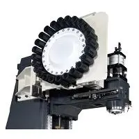
| Tool magazine capacity | 24T |
| Max diameter/length/weight of tool | Ø110mm/300mm/15kg |
| Tool change time | 2.4s |
| Others | |
| Power capacity | 42 kV A |
| Air pressure | 6-8bar |
| Machine dimension(L x W x H) | 5665x3850x3645 mm |
| Net weight | 11000kg |
| Item 01 | Descriptions | |
| 01.01 | FANUC 0i MF 5 Plus CNC system, 2MB system memory, 15/18.5 kW spindle motor | |
| 01.02 | 3 axis roller linear guide way | |
| 01.03 | 4 guide ways on Y axis | |
| 01.04 | 6000rpm belt drive spindle,BT50 with spindle oil cooler | |
| 01.05 | 24 tools arm type tools magazine | |
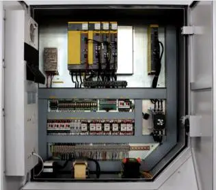
| 01.06 | Air conditioner of electrical cabinet | |
| 01.07 | Auto chip conveyer & chip chart | |
| 01.08 | Machine body washing system | |
| 01.09 | Auto oil lubrication system | |
| 01.10 | Tri-color light | |
| 01.11 | Air gun+ water gun | |
| 01.12 | Door lock switch | |
| 01.13 | Lighting lamp | |
| 01.14 | Full enclosure splash guard | |
| 01.15 | Telescopic covers |
| Item 02 | Description | Note |
| 02.01 | SIEMENS 828D 240 controller | |
| 02.02 | SIEMENS 828D 260 controller | |
| 02.03 | SIEMENS 828D 280 controller | |
| 02.04 | Siemens 15 inch CRT (touch type) | |
| 02.05 | SHOP MILL | |
| 02.06 | FANUC OI MF1 with α motor | |
| 02.07 | AICC2 + nano smoothing | Included in MF1 ,only available on MF1 |
| AICC2 400 block | Only available on MF1 | |
| Part program storage 2MB | Only available on MF1 | |
| G68.2 | Only available on MF1 | |
| Manual guide I | Only available on MF1 | |
| 3-dimensional coordinate conversion | Only available on MF1 | |
| Data serve 2GB | Only available on MF1 | |
| 10.4inch touch type ,MF1 MF3 MF5 | ||
| 15inch no touch type ,only MF1 | Only available on MF1 | |
| 15inch touch type ,only MF1 | Only available on MF1 | |
| MITSUBISHI M80B control | ||
| 02.07 | MITSUBISHI M80A control | |
| 02.08 | HEIDENHAIN 620 | 19 inch touch screen |
| 02.09 | Auto workpiece measurement, OMP60 | |
| 02.10 | Auto tool measurement RENISHAW, TS27R | |
| 02.11 | M30 auto power off | |
| 02.12 | BBT50 | |
| 02.13 | SK 50 (long delivery time ) | |
| 02.14 | CAT 50 (long delivery time ) | |
| 02.15 | 3 axis linear scale | Heidenhain |
| 02.16 | 3 axis roller guide way | |
| 02.17 | Z axis increase 300mm | Only height , not travel |
| 02.18 | 4TH axis interface | Included |
| 02.19 | CTS preare | |
| 02.20 | CTS 20 bar | Belt 6000rpm spindle |
| 02.21 | CTS 30 bar | Belt 6000rpm spindle |
| 02.22 | CTS 70 bar | Belt 6000rpm spindle |
| 02.23 | Scraping chip conveyor for aluminums cutting | |
| 02.24 | magnetic chip conveyor | |
| Oil mister collector | ||
| 30 tools magazine, arm type | ||
| 02.25 | 32 tools magazine, chain type | |
| 02.26 | Automatic tool break inspection | (must work with Renshaw tools measure ) |
| 02.27 | Auto-door( pneumatic control ) | |
| 02.28 | 2 year FANUC warranty | |
| 02.29 | 2 year Siemens warranty | |
| 02.30 | CE standard | |
| 02.31 | 380V 50HZ/415V 50 HZ /220V 60 HZ | |
| 02.32 | Transformer | |
| 02.33 | Voltage stabilizer | |
| 02.34 | Remove tools magazine | |
| 02.35 | Remove chip conveyor | |
| 02.36 | Remove chips bucket | |
| Additional Hydraulic station | ||
| Grease lubrication instead of oil | ||
| 02.37 | Pulling stud | |
| 02.38 | BT50 8000rpm ,belt | |
| 02.39 | BT40 -Belt 10,000 rpm with oil cooler | |
| 02.40 | BT50 -Direct 10,000 rpm with oil cooler | |
| 02.41 | BT40 Direct 12000 with oil cooler, without CTS , | Spindle motor 15/18.5 change to 11/15 |
| 02.42 | Direct 12000 , with CTS, FANUC | |
| BT40 Direct 12000K spindle with CTS ,SIEMENS | Spindle motor 15/18.5 change to 11/15 | |
| 02.43 | BT40 Direct 15000, water cooler motor , with CTS, Siemens | Spindle motor 15/18.5 change to 11/15 |
| 02.44 | ZF gear box | |
| 02.45 | Change BT50 6000 to BT40 8000rpm ,no oil cooler | O.D 155mm |
| ● Standard ○ Optional X N/A | ||||||
| No. | Item | Spec. | S828D | |||
| SW24x | SW26x | SW28x | ||||
| 1 | Controlled axis | Controlled axes | 3 axes | X, Y, Z | X, Y, Z | X, Y, Z |
| 2 | Additional controlled axes | 5 | 6+2 | 8+2 | ||
| 3 | Least command increment | 0.001mm (0.0001 inch) | ● | ● | ● | |
| 4 | Least input increment | 0.001mm (0.0001 inch) | ● | ● | ● | |
| 5 | Travel to fixed stop with Force Control | ○ | ○ | ○ | ||
| 6 | Interpolation & Feed Function | Reference point return | G75 FP=1 | ● | ● | ● |
| 7 | 2nd reference point return | G75 FP=2 | ● | ● | ● | |
| 8 | Inverse time feedrate | G93 | ● | ● | ● | |
| 9 | Helical interpolation | ● | ● | ● | ||
| 10 | Polynomial interpolation | X | X | X | ||
| 11 | Spline interpolation (A, B and C splines) | ○ | ○ | ○ | ||
| 12 | Separate path feed for corners and chamfers | ● | ● | ● | ||
| 13 | Acceleration with Jerk limitation | ● | ● | ● | ||
| 14 | Compressor for 3-axis machining | ● | ● | ● | ||
| 15 | Temperature compensation | ● | ● | ● | ||
| 16 | Look Ahead, recorded part program blocks: | Milling with MDynamics Advanced Surface | 150 | 300 | 450 | |
| 17 | Milling with MDynamics Top Surface | 600 | 600 | 600 | ||
| 18 | Look Ahead, IPO blocks, buffered: | Milling with MDynamics Advanced Surface | 50 | 100 | 150 | |
| 19 | Milling with MDynamics Top Surface | 200 | 200 | 200 | ||
| 20 | Cartesian point-to-point (PTP) travel | ● | ● | ● | ||
| 21 | TRANSMIT/cylinder surface transformation | ○ | ○ | ○ | ||
| 22 | Spindle Function | Tapping with compensating chuck/rigid tapping | ● | ● | ● | |
| 23 | Tool Function | Tool radius compensations in plane | ● | ● | ● | |
| 24 | Number of tools/cutting edges in tool list | 128/256 | 256/512 | 768/1536 | ||
| 25 | Tool length compensation | ● | ● | ● | ||
| 26 | Operation with tool management | ○ | ○ | ○ | ||
| 27 | Tool list | ● | ● | ● | ||
| 28 | Replacement tools for tool management | ○ | ○ | ○ | ||
| 29 | Monitoring of tool life and workpiece count | ● | ● | ● | ||
| 30 | Manual measurement of tool offset | ● | ● | ● | ||
| 31 | Magazine list | ● | ● | ● | ||
| 32 | Programming & Editing Function | Number of levels for skip blocks 2 | ● | ● | ● | |
| 33 | Number of levels for skip blocks 10 | ○ | ○ | ○ | ||
| 34 | Program/workpiece management | On additional plug-in CF card | ● | ● | ● | |
| 35 | On USB storage medium (e.g. disk drive, USB stick) | ● | ● | ● | ||
| 36 | On network drive | ○ | ○ | ○ | ||
| 37 | Program editor | Programming support for cycles program(Program Guide) | ● | ● | ● | |
| 38 | CNC editor with editing functions: select, copy, delete | ● | ● | ● | ||
| 39 | Programming graphics/free contour input (contour calculator) | ● | ● | ● | ||
| 40 | ShopMill Machining step programming | ○ | ○ | ○ | ||
| 41 | Technology cycles for drilling/milling | ● | ● | ● | ||
| 42 | Pocket milling free contour and islands stock removal cycle | ○ | ● | ● | ||
| 43 | Residual material detection | ○ | ○ | ○ | ||
| 44 | Access protection for cycles | ○ | ○ | ○ | ||
| 45 | Programming support can be extended, e.g. customer cycles | ● | ● | ● | ||
| 46 | 2D simulation | ● | ● | ● | ||
| 47 | 3D simulation, finished part | ○ | ○ | ○ | ||
| 48 | OTHERS FUNCTIONS (Operation, setting & Display, etc) |
Switchover: inch/metric | ● | ● | ● | |
| 49 | Manual measurement of zero/work offset | ● | ● | ● | ||
| 50 | Automatic tool/workpiece measurement | ● | ● | ● | ||
| 51 | Reference point approach, automatic/via CNC program | ● | ● | ● | ||
| 52 | Execution from USB or CF card interface on operator panel front | ● | ● | ● | ||
| 53 | Execution from network drive | ○ | ○ | ○ | ||
| 54 | 10.4" color display | ● | ● | ● | ||
| 55 | 15.0" color display | ○ | ○ | ○ | ||
| 56 | Alarms and messages | ● | ● | ● | ||
| 57 | Automatic measuring cycles | ○ | ○ | ○ | ||
| ● Standard ○ Optional X N/A | ||||
| NO. | Item | Spec. | TNC 620 | |
| 1 | Axes | Controlled axes | 3 axes | X, Y, Z |
| 2 | Additional Controlled axes | Max. 5 axes in total | ○ (Max. 5axes) | |
| 3 | Least command increment | 0.0001 mm (0.0001 inch), 0.0001° | ● | |
| 4 | Least input increment | 0.0001 mm (0.0001 inch), 0.0001° | ● | |
| 5 | MDI / DISPLAY unit | 19 "color flat-panel display, vertical, touch screen (for MC 8410) | ● | |
| 6 | Program memory for NC programs | 1.8GB | ||
| 7 | CFR CF memory card | 8GB | ||
| 8 | Commissioning and diagnostics | Data interfaces | Ethernet interface | ● |
| 9 | USB interface (USB 2.0) | ● | ||
| 10 | Machine functions | Look-ahead (Intelligent path control by calculating the path speed ahead of time) |
Max. 5000 blocks. | ● |
| 11 | User functions | Brief description | Basic version: 3 axes plus spindle | ● |
| 12 | One or two additional NC axes | ○ | ||
| 13 | Digital current and spindle speed control | ● | ||
| 14 | Program entry | HEIDENHAIN conversational and DIN/ ISO formats | ● | |
| 15 | Position data coordinates | Nominal positions for lines and arcs in Cartesian coordinates or polar coordinates | ● | |
| 16 | Incremental or absolute dimensions | ● | ||
| 17 | Display and input in mm or inches | ● | ||
| 18 | Tool compensation | Tool radius in the working plane and tool length | ● | |
| 19 | Radius-compensated contour look-ahead for up to 99 blocks (M120) | ○ | ||
| 20 | Three-dimensional tool-radius compensation for changing tool data without having to recalculate an existing program |
○ | ||
| 21 | Tool tables | Multiple tool tables with any number of tools | ● | |
| 22 | Constant contour speed | Relative to the path of the tool center | ● | |
| 23 | Relative to the tool’s cutting edge | ● | ||
| 24 | Parallel operation | Creating a program with graphical support while another program is being run | ● | |
| 25 | 3-D machining | Motion control with minimum jerk | ○ | |
| 26 | 3-D tool compensation through surface normal vectors | ○ | ||
| 27 | Keeping the tool normal to the contour | ○ | ||
| 28 | Tool radius compensation normal to the tool direction | ○ | ||
| 29 | Contour elements | Straight line | ● | |
| 30 | Chamfer | ● | ||
| 31 | Circular path | ● | ||
| 32 | Circle center point | ● | ||
| 33 | Circle radius | ● | ||
| 34 | Tangentially connecting circular arc | ● | ||
| 35 | Corner rounding | ● | ||
| 36 | Approaching and departing the contour | Via straight line: tangential or perpendicular | ● | |
| 37 | Via circular arc | ● | ||
| 38 | Program jumps | Subroutines | ● | |
| 39 | Program section repeats | ● | ||
| 40 | Calling any program as subroutine | ● | ||
| 41 | Coordinate transformation | Datum shift, rotation, mirror image, scaling factor (axis-specifi c) | ● | |
| 42 | Tilting the working plane, PLANE function | ○ | ||
| 43 | Actual position capture | Actual positions can be transferred directly into the NC program | ● | |
| 44 | Programming graphics | In the Programming and Editing mode, the contour of the NC blocks is drawn on screen while the blocks are being entered (2-D pencil-trace graphics), even while another program is running |
● | |
| 45 | Machining time | Calculation of machining time in the Test Run operating mode Display of the current machining time in the Program Run operating modes |
● | |
| 46 | Returning to the contour | Mid-program startup in any block in the program, returning the tool to the calculated nominal position to continue machining |
● | |
| 47 | Program interruption, leaving and returning to the contour | ● | ||
| 48 | Preset tables | One preset table for storing reference points | ● | |
| 49 | Datum tables | Several datum tables for storing workpiece-related datums | ● | |
| 50 | Parallel secondary axes | Compensating movement in the secondary axis U, V, W through the principal axis X, Y, Z | ● | |
| 51 | Including movements of parallel axes in the position display of the associated principal axis (sum display) | ● | ||
| 52 | Defi ning the principal and secondary axes in the NC program makes it possible to run programs on different machine confi gurations |
● | ||
| 53 | Conversational languages | English, Chinese (traditional, simplifi ed), Czech, Danish, Dutch, Finnish, French, German, Hungarian, Italian, Polish, Portuguese, Russian (Cyrillic), Spanish, Swedish |
● | |
| 54 | Fixed cycles | Drilling, conventional and rigid tapping, rectangular and circular pockets | ● | |
| 55 | Peck drilling, reaming, boring, counter boring, (centering) | ○ | ||
| 56 | Milling internal and external threads | ○ | ||
| 57 | Clearing level and oblique surfaces | ○ | ||
| 58 | Multi operation machining of straight and circular slots | ○ | ||
| 59 | Multioperation machining of rectangular and circular pockets | ○ | ||
| 60 | Linear and circular point patterns | ○ | ||
| 61 | Contour train, contour pocket—also with contour-parallel machining | ○ | ||
| 62 | OEM cycles (special cycles developed by the machine tool builder) can be integrated | ○ | ||
| 63 | Touch probe cycles | Touch probe calibration | ○ | |
| 64 | Compensation of workpiece misalignment,manual or automatic | ○ | ||
| 65 | Datum setting, manual or automatic | ○ | ||
| 66 | Automatic tool and workpiece measurement | ○ | ||
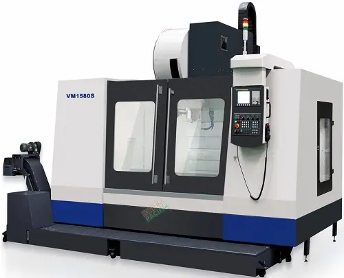
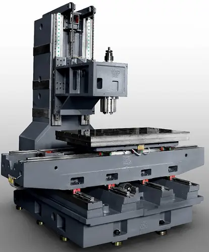
The VM1580S Vertical Machining Center by Fortune Pacific is a high-performance CNC machine designed for precision metalworking. This robust 3-axis milling machine features a rigid box-way construction, 15HP spindle motor, and 8000 RPM speed for heavy-duty cutting. Key specs include X/Y/Z travels of 1500×800×600mm, 24-station automatic tool changer, and 0.005mm positioning accuracy. Ideal for mold making, aerospace parts, and automotive components, this industrial-grade VMC offers superior stability with its cast iron base and linear guideways. Operators appreciate the user-friendly Fanuc control system, flood coolant system, and optional 4th axis rotary table. Common search terms include "CNC vertical mill", "precision machining center", and "industrial milling machine".
Вертикальный обрабатывающий центр VM1580S от Fortune Pacific - это профессиональный фрезерный станок с ЧПУ для металлообработки. Станок с жесткой коробчатой станиной и линейными направляющими обеспечивает точность до 0,005 мм. Основные характеристики: ход по осям 1500×800×600 мм, автоматический сменщик инструмента на 24 позиции, скорость шпинделя 8000 об/мин. Идеален для производства пресс-форм, аэрокосмических деталей и автокомпонентов. В народе такие станки называют "фрезерный ЧПУ" или "обрабатывающий центр". Ключевые преимущества: система охлаждения, опция 4-й оси и надежная система управления Fanuc.
El centro de mecanizado vertical VM1580S de Fortune Pacific es una máquina CNC industrial de alta precisión para fresado de metales. Con estructura de fundición robusta y guías lineales, ofrece recorridos de 1500×800×600mm en ejes X/Y/Z. Incluye cambiador automático de herramientas de 24 posiciones, husillo de 8000 RPM y control Fanuc. Perfecto para moldes, componentes aeroespaciales y piezas automotrices. Conocido coloquialmente como "fresadora CNC vertical" o "centro de maquinado". Entre sus ventajas destacan la alta rigidez, precisión de 0,005mm y opción de mesa rotativa de 4º eje. Términos de búsqueda comunes: "máquina de fresado industrial", "centro de mecanizado preciso".
O centro de usinagem vertical VM1580S da Fortune Pacific é uma máquina CNC profissional para fresagem de metais. Com estrutura rígida em ferro fundido e guias lineares, oferece precisão de 0,005mm e curso de 1500×800×600mm. Equipado com trocador automático de ferramentas de 24 posições, spindle de 15HP e 8000 RPM. Ideal para moldes, componentes aeroespaciais e peças automotivas. No mercado é conhecido como "fresa CNC vertical" ou "centro de usinagem CNC". Principais vantagens: sistema Fanuc, opção de 4º eixo e alta produtividade. Termos populares: "máquina de usinagem industrial", "centro de fresagem CNC".
Mesin bubut vertikal VM1580S dari Fortune Pacific adalah pusat permesinan CNC presisi tinggi untuk logam. Dengan konstruksi besi cor dan guide linear, memiliki akurasi 0,005mm dan area kerja 1500×800×600mm. Dilengkapi automatic tool changer 24 alat, spindle 8000 RPM dan kontrol Fanuc. Cocok untuk mold, komponen aerospace dan otomotif. Dikenal sebagai "mesin milling CNC" atau "mesin bubut vertikal". Keunggulan: sistem pendingin, opsi rotary table dan stabilitas tinggi. Istilah pencarian: "mesin CNC industri", "pusat permesinan presisi".
مرکز ماشینکاری عمودی VM1580S از فورچون پاسیفیک یک دستگاه CNC صنعتی با دقت بالا برای فرزکاری فلزات است. این دستگاه با ساختار محکم چدنی و راهنماهای خطی، دقت 0.005 میلیمتر و محدوده کاری 1500×800×600 میلیمتر ارائه میدهد. مجهز به سیستم تعویض ابزار خودکار 24 موقعیتی، اسپیندل 8000 دور در دقیقه و کنترل فانوک. اصطلاحات رایج جستجو: "دستگاه فرز CNC صنعتی"، "مرکز ماشینکاری دقیق".
Máy phay đứng VM1580S của Fortune Pacific là trung tâm gia công CNC chính xác cao cho kim loại. Với kết cấu bàn máy gang và hệ thống ray trượt, đạt độ chính xác 0.005mm và hành trình 1500×800×600mm. Trang bị bộ đổi dao tự động 24 vị trí, trục chính 8000 vòng/phút và điều khiển Fanuc. Phù hợp gia công khuôn mẫu, linh kiện hàng không và ô tô. Ưu điểm: hệ thống làm mát, tùy chọn trục xoay thứ 4. Từ khóa tìm kiếm: "máy phay CNC công nghiệp", "trung tâm gia công chính xác".
เครื่องกัดแนวตั้ง VM1580S จาก Fortune Pacific เป็นเครื่อง CNC ความแม่นยำสูงสำหรับงานโลหะ ด้วยโครงสร้างเหล็กหล่อและระบบนำแนวเส้นตรง ให้ความแม่นยำ 0.005 มม. พร้อมระยะทำงาน 1500×800×600 มม. ประกอบด้วยเครื่องเปลี่ยนมีดอัตโนมัติ 24 ตัว สปินเดิล 8000 รอบ/นาที และระบบควบคุม Fanuc เหมาะสำหรับงานแม่พิมพ์ ชิ้นส่วนอากาศยานและยานยนต์ ข้อดี: ระบบหล่อเย็น ตัวเลือกโต๊ะหมุนและความเสถียรสูง คำค้นหายอดนิยม: "เครื่องกัด CNC อุตสาหกรรม", "ศูนย์เครื่องมือกลความละเอียดสูง".
Mesin pengilangan menegak VM1580S dari Fortune Pacific ialah pusat pemesinan CNC ketepatan tinggi untuk logam. Dengan struktur besi tuang dan panduan linear, menawarkan ketepatan 0.005mm dan pergerakan 1500×800×600mm. Dilengkapi penukar alat automatik 24 stesen, spindel 8000 RPM dan kawalan Fanuc. Sesuai untuk acuan, komponen aeroangkasa dan automotif. Dikenali sebagai "mesin CNC pengilangan" atau "pusat pemesinan industri". Kelebihan: sistem penyejuk, pilihan meja putar dan ketahanan tinggi. Istilah carian: "mesin pengilangan industri", "pusat pemesinan tepat".
O centro de usinagem vertical VMC1580S da Fortune Pacific é uma máquina de alto desempenho perfeita para oficinas de usinagem pesada. Equipado com um eixo principal de 12.000 rpm e curso XYZ de 1500x800x600mm, este centro de maquinação CNC oferece precisão micronizada graças aos guias lineares de alta rigidez e sistema de controle FANUC. Popularmente chamado de "fresadora CNC industrial" ou "máquina de corte vertical", é amplamente utilizado na fabricação de moldes, componentes aeroespaciais e peças automotivas complexas. Seus diferenciais incluem trocador automático de ferramentas (ATC) com 24 posições, mesa de trabalho reforçada para cargas pesadas e sistema de refrigeração integrado. Termos como "maquinário CNC premium", "fresadora de bancada fixa" e "equipamento para usinagem de alumínio" são frequentemente associados a este modelo pelos compradores brasileiros.
Ang vertical machining center na VMC1580S mula sa Fortune Pacific ay isang high-performance na makina na perpekto para sa heavy-duty machining. Kilala rin bilang "CNC milling machine" o "industrial router", ito ay may 12,000 rpm spindle speed at malaking working area na 1500x800x600mm. Ang makina na ito ay espesyal na dinisenyo para sa paggawa ng mga precision parts gaya ng aerospace components, automotive molds, at medical equipment. Maraming bumibili ang naghahanap sa mga katagang tulad ng "matibay na CNC machine", "mataas na bilis na milling center", at "automated machining equipment" kapag naghahanap ng ganitong klaseng makina sa Pilipinas. Ang key features nito ay may kasamang 24-tool ATC, rigid box-way construction, at advanced FANUC control system para sa pinakamahusay na accuracy at repeatability.
Il centro di lavorazione verticale VMC1580S di Fortune Pacific rappresenta l'eccellenza nel campo delle macchine utensili CNC. Chiamato comunemente "fresatrice CNC industriale" o "centro di lavoro verticale", questo modello offre prestazioni eccezionali con i suoi 12.000 giri/min del mandrino e un'area di lavoro generosa di 1500x800x600mm. Particolarmente apprezzato nell'industria metalmeccanica per la produzione di stampi, componenti aerospaziali e pezzi automobilistici complessi. I termini di ricerca più utilizzati includono "macchina CNC ad alta precisione", "fresatrice a controllo numerico" e "centro di lavorazione verticale per metalli duri". Dotato di cambio utensile automatico a 24 posizioni, guide lineari rinforzate e sistema di raffreddamento integrato, è la scelta ideale per chi cerca affidabilità e precisione micronometrica.
Fortune Pacific'ın VMC1580S dikey işleme merkezi, ağır sanayi uygulamaları için tasarlanmış yüksek performanslı bir CNC tezgahıdır. "Endüstriyel freze makinesi" veya "CNC işleme merkezi" olarak da bilinen bu model, 12.000 dev/dk spindle hızı ve 1500x800x600mm çalışma alanı sunar. Özellikle kalıpçılık, havacılık parçaları ve otomotiv endüstrisinde tercih edilir. Türk pazarında "yüksek hassasiyetli CNC", "otomatik takım değiştiricili işleme merkezi" ve "sert metaller için freze makinesi" gibi anahtar kelimelerle aranır. 24 takımlık ATC sistemi, rijit yapısı ve FANUC kontrol ünitesiyle dikkat çeker. Kullanıcıların en çok önem verdiği özellikler arasında yüksek kesme hızı, mikron seviyesinde hassasiyet ve uzun ömürlü dayanıklılık bulunur.
Le centre d'usinage vertical VMC1580S de Fortune Pacific est une machine CNC haut de gamme idéale pour l'usinage de précision. Appelé couramment "fraiseuse CNC industrielle" ou "centre d'usinage à commande numérique", ce modèle se distingue par sa broche de 12 000 tr/min et sa grande course de 1500x800x600mm. Très prisé dans la fabrication de moules, de composants aéronautiques et de pièces automobiles complexes. Les termes comme "machine-outil haute précision", "centre d'usinage vertical performant" et "équipement CNC professionnel" sont souvent recherchés par les acheteurs francophones. Ses atouts majeurs incluent un changeur d'outils automatique 24 positions, des glissières linéaires renforcées et un système de contrôle FANUC pour une précision micronique.
مركز التشغيل الرأسي VMC1580S من فورتشن باسيفيك هو آلة CNC عالية الأداء مثالية للأعمال الصناعية الثقيلة. يعرف هذا الجهاز في السوق العربي باسم "ماكينة CNC رأسي" أو "فريزة صناعية" ويتميز بسرعة مغزل تصل إلى 12000 دورة في الدقيقة ومساحة عمل 1500x800x600 مم. يستخدم على نطاق واسع في تصنيع القوالب والمكونات الفضائية وقطع السيارات المعقدة. تشمل المصطلحات الشائعة في البحث "ماكينات CNC دقيقة"، "مراكز تشغيل معادن" و"معدات تصنيع متطورة". يتميز الجهاز بنظام تغيير أدوات آلي 24 موقعًا، وهيكل صلب ومتحكم FANUC لضمان أعلى مستويات الدقة والموثوقية التي يبحث عنها العملاء في الشرق الأوسط.
Die VMC1580S Vertikal-Bearbeitungszentrum von Fortune Pacific ist eine Hochleistungs-CNC-Maschine für die Metallbearbeitung. Bekannt als "Industrie-Fräsmaschine" oder "CNC-Bearbeitungscenter", überzeugt es mit 12.000 U/min Spindeldrehzahl und großem Arbeitsbereich von 1500x800x600mm. Besonders geeignet für den Formenbau, Luftfahrtteile und anspruchsvolle Automobilkomponenten. Suchbegriffe wie "Präzisions-CNC-Maschine", "automatische Werkzeugwechsler" und "hochentwickelte Frästechnologie" sind im deutschen Markt relevant. Das System bietet 24-Werkzeugmagazin, stabile Führungsschienen und FANUC-Steuerung für mikrometergenaue Ergebnisse. Deutsche Kunden legen besonderen Wert auf deutsche Qualitätsstandards, Energieeffizienz und langfristige Zuverlässigkeit.
Het VMC1580S verticale bewerkingscentrum van Fortune Pacific is een krachtige CNC-machine voor zware industriele toepassingen. In de Nederlandse markt vaak aangeduid als "industriële freesmachine" of "CNC bewerkingscentrum", beschikt dit model over een 12.000 toeren spindle en groot werkbereik van 1500x800x600mm. Bijzonder geschikt voor matrijzen, aerospace-onderdelen en complexe auto-onderdelen. Zoektermen zoals "hoogwaardige CNC machines", "precisie bewerkingscentra" en "automatische gereedschapswisselaars" zijn populair onder Nederlandse kopers. Belangrijke kenmerken zijn het 24-gereedschappen ATC-systeem, stijve constructie en geavanceerd FANUC besturingssysteem voor uitzonderlijke nauwkeurigheid en productiviteit.
Centrum obróbcze VMC1580S od Fortune Pacific to zaawansowana maszyna CNC do precyzyjnej obróbki metali. Na polskim rynku znana jako "frezarka CNC przemysłowa" lub "obrabiarka sterowana numerycznie", oferuje prędkość wrzeciona 12 000 obr/min i duży obszar roboczy 1500x800x600mm. Idealna do produkcji form, części lotniczych i skomplikowanych elementów samochodowych. Polscy klienci często szukają haseł takich jak "profesjonalne centrum frezarskie", "maszyna CNC do aluminium" i "automatyczna wymiana narzędzi". Kluczowe cechy to 24-narzędziowy magazyn, sztywna konstrukcja i system sterowania FANUC gwarantujący mikronową dokładność, co jest szczególnie cenione w polskim przemyśle metalowym.
Centrul de prelucrare vertical VMC1580S de la Fortune Pacific este o mașină CNC de înaltă performanță pentru aplicații industriale grele. Cunoscut pe piața românească sub denumirile "freză CNC industrială" sau "centru de prelucrare vertical", acest model oferă viteză spindle de 12.000 rpm și o suprafață de lucru generoasă de 1500x800x600mm. Utilizat în special pentru fabricarea matrițelor, componentelor aerospațiale și pieselor auto complexe. Termenii căutate frecvent includ "mașini CNC de precizie", "centre de prelucrare cu comandă numerică" și "echipamente pentru prelucrare metale". Dotat cu schimbător automat de scule cu 24 de poziții, ghidaje lineare robuste și sistem de control FANUC, asigură acuratețe micronică și fiabilitate ridicată - cerințe cheie pentru clienții români din industria metalurgică.
A Fortunepacific VM1580S vertikális megmunkáló központ a nehézipari megmunkálás csúcstechnológiáját képviseli. Ez a CNC vezérlésű gépgárda kiválóan alkalmas összetett alkatrészek precíziós megmunkálására, legyen szó akár szerszámgépekről, formákról vagy repülőgép-alkatrészekről. A gép főbb paraméterei között megtalálható a 1500×800×700 mm-es X-Y-Z tengelyműködés, 8000 ford/perc orsófordulat és 0,005 mm pozicionálási pontosság. A merev vasszerkezet és a lineáris vezetékrendszer garantálja a hosszú élettartamot és stabil megmunkálási minőséget. A gépet Siemens 828D vezérlőrendszerrel szerelik, ami lehetővé teszi a 5 tengelyű megmunkálást is későbbi bővítésként. Különösen népszerű a magyar gépipari vállalkozások körében a "precíziós maró" vagy "CNC marógép" elnevezéssel, ahol a nagy orsóteljesítmény és a korszerű szervómeghajtás előnyeit kihasználják.
Το κατακόρυφο κέντρο επεξεργασίας Fortunepacific VM1580S είναι μια κορυφαία λύση για βιομηχανικές εφαρμογές υψηλής ακρίβειας. Με ισχυρή δομή από χυτοσίδηρο και γραμμικούς οδηγούς, αυτό το CNC μηχάνημα παρέχει αξιοπιστία και σταθερότητα σε μακροπρόθεσμη χρήση. Οι κύριες παράμετροι περιλαμβάνουν εμβαδόν επεξεργασίας 1500×800 mm, μέγιστο ύψος επεξεργασίας 700 mm και ταχύτητα ατράκτου έως 8000 rpm. Το σύστημα ελέγχου Siemens 828D προσφέρει προηγμένες λειτουργίες όπως η αυτόματη αντιστάθμιση εργαλείων και η 3D προσομοίωση. Γνωστό στην ελληνική αγορά ως "κατακόρυφο κέντρο μηχανουργικής" ή "CNC μηχάνημα μετάλλου", είναι ιδανικό για την παραγωγή καλουπιών, αεροναυτικών εξαρτημάτων και ιατρικών οργάνων. Η συμπαγής σχεδίαση και το σύστημα ψύξης υψηλής απόδοσης το καθιστούν ιδανική επιλογή για Ελληνικές βιομηχανίες που αναζητούν "ακριβή μηχανική επεξεργασία" με μειωμένο χρόνο κύκλου.
Fortunepacific VM1580S vertikální obráběcí centrum představuje špičkové řešení pro náročné obrábění kovů. S pracovním prostorem 1500×800×700 mm a rychlostí vřetena až 8000 ot/min je tento stroj ideální pro výrobu forem, leteckých komponentů a přesných strojních dílů. Konstrukce z těžkého litinového rámu zajišťuje vynikající vibrační absorbci a stabilitu. Lineární vedení a výkonné servopohony dosahují pozicování s přesností 0,005 mm. V českém průmyslu je známý pod přezdívkami "CNC frézka" nebo "vertikální fréza", přičemž klíčové výhody zahrnují nízké provozní náklady a možnost rozšíření na 5osé obrábění. Siemens 828D ovládací systém nabízí uživatelsky přívětivé rozhraní a pokročilé funkce jako adaptivní obrábění. Toto obráběcí centrum je vyhledáváno českými výrobci pro svou "vysokou produktivitu" a "dlouhou životnost", zejména při sériové výrobě.
Вертикалният machining център Fortunepacific VM1580S е индустриално решение за високоскоростна обработка на метали. С работна площ от 1500×800 mm и Z-ход от 700 mm, този CNC струг е идеален за производство на матрици, авиационни компоненти и прецизни части. Основната конструкция включва тежък чугунен корпус с линейни водачи за повишена стабилност. Връхната скорост на шпиндела достига 8000 об/мин при точност на позициониране 0,005 mm. В българския пазар машината е известна като "CNC фреза" или "вертикален струг", като се цени за надеждната Siemens 828D управляваща система и възможността за 5-осна обработка. Автоматичната смяна на инструменти (24-мяста магазина) и системата за охлаждане повишават производителността, което го прави популярен избор за български предприятия търсещи "високоскоростна металообработка" с "оптимална точност".
Fortunepacific VM1580S vertikalni mašinski centar predstavlja vrhunsko rešenje za preciznu obradu metala. Sa radnim prostorom od 1500×800×700 mm i brzinom vretena do 8000 o/min, ovaj CNC stroj je idealan za proizvodnju kalupa, avionskih komponenti i preciznih delova. Čelična konstrukcija sa linearnim vodilicama obezbeđuje izuzetnu stabilnost i dugotrajnu preciznost. U srpskoj industriji ovaj stroj je poznat pod nazivima "CNC glodalica" ili "vertikalna glodalica", posebno cenjen zbog Siemens 828D upravljačkog sistema koji podržava 3D simulaciju. Ključne prednosti uključuju automatsku promenu alata (24 pozicije), sistem za hlađenje i mogućnost nadogradnje na 5-osnu obradu. Srpski proizvođači često traže "brzu obradu metala" sa "minimalnim otpadom", što ovaj model optimalno ispunjava zahvaljujući naprednoj kontroli parametara rezanja.
Vertikálne obrábacie centrum Fortunepacific VM1580S je špičkové CNC zariadenie pre presné obrábanie kovov. S pracovným priestorom 1500×800 mm a maximálnou rýchlosťou vretena 8000 ot/min sa výborne hodí na výrobu foriem, leteckých súčiastok a presných strojových dielov. Ťažká liatinová konštrukcia s lineárnymi vedeniami zaisťuje vynikajúcu stabilitu aj pri náročných obrábacích operáciách. Na slovenskom trhu je známy ako "CNC frézka" alebo "vertikálna fréza", pričom hlavné výhody zahŕňajú nízke prevádzkové náklady a možnosť rozšírenia na 5-osové obrábanie. Siemens 828D riadiaci systém ponúka pokročilé funkcie ako adaptívne obrábanie a automatickú kompenzáciu opotrebenia nástrojov. Slovenskí výrobcovia oceňujú najmä "vysokú produktivitu" a "dlhú životnosť" tohto stroja pri sériovej výrobe.
Fortunepacific VM1580S vertikalni glodalni center je vrhunska rešitev za visoko natančno obdelavo kovin. Z delovnim prostorom 1500×800×700 mm in hitrostjo vretena do 8000 vrt/min je ta CNC stroj idealen za izdelavo kalupov, letalskih komponent in natančnih delov. Konstrukcija iz težke lite železa z linearnimi vodili zagotavlja izjemno stabilnost in dolgo življenjsko dobo. V slovenskem industriji je stroj znan kot "CNC rezalni stroj" ali "vertikalna glodalica", posebej cenjen zaradi sistema Siemens 828D, ki omogoča 3D simulacijo. Ključne prednosti vključujejo avtomatsko menjavo orodja (24 položajev), visoko natančnost pozicioniranja 0,005 mm in možnost nadgradnje na 5-osno obdelavo. Slovenska podjetja iščejo predvsem "zanesljive stroje" za "serijsko proizvodnjo", kar ta model izpolnjuje z visoko hitrostjo obdelave in minimalnimi odpadi materiala.
Вертикальний обробний центр Fortunepacific VM1580S - це високотехнологічне рішення для прецизійної обробки металів. З робочим полем 1500×800×700 мм та швидкістю шпінделя до 8000 об/хв, цей верстат з ЧПУ ідеально підходить для виготовлення прес-форм, авіакомпонентів та точних деталей. Важка чавунна конструкція з лінійними напрямними забезпечує високу стабільність під час обробки. На українському ринку цей станок відомий як "вертикально-фрезерний" або "фрезерний станок з ЧПУ", особливо цінується за систему керування Siemens 828D, яка підтримує 5-вісну обробку. Автоматична зміна інструменту (24 позиції) та система охолодження підвищують продуктивність, що робить його ідеальним вибором для українських підприємств, які шукають "високошвидкісну обробку металів" з "мінімальним браком".