| Item | Unit | Specification | Remark | |
| Machining range | Width of table | mm | 3000 | |
| Length of table | mm | 6000 | ||
| Max. Load of table | kg | 34000 | ||
| Effective width of gantry | mm | 3800 | ||
| Max. Height of the gantry | mm | 1500 | ||
| Distance between vertical spindle to table surface | mm | 250~1500 | standard | |
| mm | 250~1750 | optional | ||
| Table travel | Max. Table Travel - X | mm | 6200 | |
| Max. Slider travel-Y | mm | 4200 | ||
| Max. Ram travel-Z | mm | 1250 | standard | |
| Max. Ram travel-Z | mm | 1500 | optional | |
| T slot | quantity-width-distance | 13-28-220 | ||
| Spindle | Drive type | direct drive spindle+ gear box | ||
| power | kW | 31/37 | ||
| Highest speed | rpm | 4000 | Z travel 1250 | |
| rpm | 3000 | Optional Z travel 1500 | ||
| Rated torque | N.m | 718 | ||
| Max. torque | N.m | 849 | ||
| Max. broach | N | 18000 | ||
| taper | BT50 | |||
| Spindle speed control method | stepless | |||
| CTS pressure | MPa | 2/3/5 | optional | |
| Table system (X) | Structure type | Table movement | ||
| Guideway type | Heavy linear guide rail pair | 65mm | ||
| Quantity of rail pair | set | 2 | ||
| Transmission form | Planetary reducer | |||
| Reduction ratio | 1:7 | |||
| Drive unit | Ball screw pair | φ100×20/C3 | ||
| Saddle system (Y) | Structure type | Saddle movement | ||
| Guideway type | Heavy linear guide rail pair | 55mm | ||
| Quantity of rail pair | set | 2 | ||
| Transmission form | Planetary reducer | |||
| Reduction ratio | 1:4 | |||
| Drive unit | Ball screw pair | φ63×16/C3 | ||
| Ram system (Z) | Structure type | ram movement | ||
| Guideway type | Square ram guide way | 450mmx450mm | ||
| Transmission form | Planetary reducer | |||
| Reduction ratio | 1:4 | |||
| Drive unit | Ball screw pair | φ63×12/C3 | ||
| Feed motor (power, torque) |
X servo motor | 7KW, 30N.m | ||
| Y servo motor | 4KW, 22N.m | |||
| Z servo motor | 4KW, 22N.m | |||
| Rapid feed speed | Table longitudinal movement X axis | mm/min | 10000 | |
| Saddle cross movement Y axis |
mm/min | 10000 | ||
| Ram vertical movement Z axis |
mm/min | 8000 | ||
| Cutting feed speed | X, Y, Z | mm/min | 1-4000 | |
| CNC system | System | FANUC Oi MF Plus | ||
| The total number of control axis | Axes | 3 | ||
| Linkage control axis number | Axes | 3 | ||
| Hand crank pulse generator | include | |||
| Hand crank device with self-locking | include | |||
| interface | Ethernet, CF card/USB | |||
| Network card interface | DNC networking, data acquisition | |||
| Tool magazine | Tool holder | BT50 | ||
| Type | Arm type/24pcs | |||
| Max. Tool weight | kg | 25 | ||
| Max. Tool length | mm | 350 | ||
| Max. Tool dia.(full) | mm | 110 | ||
| Max. Tool dia. (adjacent empty) | mm | 220 | ||
| Auxiliary function | Lubrication type of guideway pair/ball screw pair | automatic centralized lubrication | ||
| Operation panel | suspended | |||
| Operation type of manual tool change | Control by button | |||
| Status indication | Three-colour warning lamp | |||
| Cooling type | External cooling | |||
| Safety door | Tempered Glass | |||
| Positioning accuracy of linear axis (GB/T19362.1-2003) | X | mm | 0.042 | |
| Y | mm | 0.032 | ||
| Z | mm | 0.025 | ||
| Repeat Positioning accuracy of linear axis (GB/T19362.1-2003) |
X | mm | 0.030 | |
| Y | mm | 0.020 | ||
| Z | mm | 0.015 | ||
| Working accuracy | Fine boring surface roughness | ≤Ra1.6 | HB230~260 steel | |
| Fine milling surface roughness | ≤Ra3.2 | |||
| Machine size | Length | mm | 15120 | |
| Width | mm | 6500 | ||
| Height | mm | 6500 | Z travel 1250mm | |
| mm | 6800 | Z travel 1500mm | ||
| Electrical capacity | KVA | 45 | ||
| Gas consumption of machine | m3/h | 20 | ||
| Machine air source pressure | MPa | 0.6-0.8 | ||
| Machine weight(about) | kg | 90000 | Z travel 1250 | |
| kg | 91500 | Z travel 1500 | ||
| Item 01 | Descriptions |
| 01.01 | FANUC Oi-MF 1 CNC system |
| 01.02 | Taiwan direct connect type spindle 6000rpm (highest speed 3000rpm), BT50 |
| 01.03 | Taiwan X roller linear guide way, Y linear guide , Z box guide way |
| 01.04 | Taiwan ballscrews for X, Y, Z |
| 01.05 | Taiwan arm type tool magazine with 24 tools |
| 01.06 | Auto lubrication system |
| 01.07 | Taiwan water coolant pump |
| 01.08 | Schneider electric components |
| 01.09 | Nitrogen balance system |
| 01.10 | Air conditioner for electrical box |
| 01.11 | Water gun and air gun |
| 01.12 | Screw Chip conveyor |
| Item 02 | Descriptions |
| 02.01 | Chain type chip conveyor |
| 02.02 | ZF box |
| 02.03 | CTS |
| 02.04 | Renishaw Touch Probe |
| 02.05 | Renishaw Tool Setter |
| 02.06 | 32/40/60PCS chain type tool magazine |
| FANUC 0i-MF plus function table | ||
| Servo axis control | Number of control axes | 7 |
| Simultaneous control of the number of axes | 4 | |
| Axis name | X/Y/Z/A | |
| Number of control paths | 1 | |
| Minimum input increment (unit) | X/Y/Z 0.001mm | |
| Minimum command increment (unit) | X/Y/Z 0.001mm | |
| High response vector control | HRV2, HRV3 control | |
| Metric/Imperial conversion | G20, G21 | |
| Mechanical locking | yes | |
| Emergency Stop | yes | |
| Over-travel signal and inspection | yes | |
| Servo shutdown/mechanical wheel feed | yes | |
| Abnormal load detection | yes | |
| Nano-interpolation | yes | |
| Fast feeds and cutting feeds are corrected separately | yes | |
| Positioning | G0 | |
| Spindle | Spindle speed function | S5 digits, binary output |
| Spindle speed multiplier (10% increase) | 50%~120% | |
| Spindle orientation (one position) | M19 | |
| Rigid tapping | yes | |
| Program Function | Maximum command value | +/–99999999 |
| 10x input units | yes | |
| Program file name | 32 characters | |
| Manual absolute value ON/OFF | yes | |
| Absolute/incremental programming instructions | G90/G91 | |
| Fixed Cycle | G70~G72 G74~G76 | |
| Fixed Cycle | G80~G89 | |
| Rigid tapping | M29Sxxxx | |
| Program Stop | M00, M01 | |
| Program End | M02, M30 | |
| Programmable data input | G10 | |
| Planar selection | G17, G18, G19 | |
| Workpiece coordinate system | G52~G59 | |
| Subroutine calls | 10 layers nesting | |
| User macro program public variables | yes | |
| Programmable Mirror | yes | |
| Data input/output and communication functions | Program storage capacity | 2MB |
| Number of programs that can be stored | 1000 | |
| Program protection lock | yes | |
| Background editing | yes | |
| Program number | O4 digits | |
| RS232 | yes | |
| USB memory disk input/output | yes | |
| DNC operation with memory cards | yes | |
| Embedded Ethernet | yes | |
| Feeding and auxiliary functions | Feeding mode: fast/Jog feed/manual | yes |
| Manual feed rate | ×1, ×10, ×100…×200 | |
| Rapid feed rate | F0, F25, F50, F100 | |
| Jog feed | 0~200mm | |
| Maximum cutting feed | 0~10000mm | |
| Incremental feeds | ×1~×1000 | |
| Intelligent Overlap | yes | |
| Automatic acceleration and deceleration | Rapid feed: linear type Cutting feed: exponential function type, linear type |
|
| AI Profile Control II | Yes, maximum pre-reading 200 segments | |
| Storage pitch error compensation | yes | |
| Processing condition selection function | yes | |
| Tool function | Tool shape compensation C | G40~G42 |
| Tool length compensation H | G43 | |
| Tool compensation (group) | 64 | |
| Operation | Auto operation | yes |
| MDI operation | yes | |
| DNC operation | yes | |
| Manual operation | yes | |
| Manual Home Return | yes | |
| Single-section execution | yes | |
| Selective pause | yes | |
| Quick Location | G00 | |
| Straight cutting | G01 | |
| Arc cutting | G02/G03 | |
| Pause function | G04 | |
| zero return | G28 | |
| Second origin reset | G30 | |
| Setting and display functions | Monitor | 10.4″LCD |
| Status display | yes | |
| Time Display | yes | |
| Display current position | yes | |
| Program Display | yes | |
| Display parameter setting | yes | |
| Parameter checksum function | yes | |
| Display alarm and operation information function | yes | |
| Machining time and number of parts display | yes | |
| Actual machining speed display | yes | |
| Spindle speed and T-code display | yes | |
| Graphical display | yes | |
| Standard configuration list | ||||
| No. | Name | Parameter | Qty. | Remark |
| 1 | Cnc controller | FANUC 0i-MF Plus | 1 | |
| 2 | Handheld operating unit | With emergency stop button | 1 | |
| 3 | Auto chip conveyor | Spiral chip conveyor | 2 | |
| 4 | Half protection | 1 | ||
| 5 | Spray Gun | Water gun+air gun | 1 | |
| 6 | Cooling system | 1 | ||
| 7 | Liquid nitrogen balancing system | 1 | ||
| 8 | Hydraulic station | 1 | ||
| 9 | Auto lubrication system | 1 | ||
| 10 | Pneumatic system | 1 | ||
| 11 | lighting | 1 | ||
| 12 | Three colour light | 1 | ||
| 13 | Pneumatic system | 1 | ||
| 14 | Spindle gear box | China | 1 | |
| 15 | Planetary reducer | 1 | ||
| 16 | Air conditioner | 1 | ||
| 17 | Spindle oil cooler | |||
| 18 | Accessory with machine | 1 | ||
| 19 | documents | 1 | ||
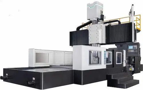
Unlock unmatched productivity with the GMC3060, a robust CNC gantry type machining center designed for heavy-duty cutting and high-precision machining. This powerful 3-axis vertical machining center (VMC) features a rigid cast iron bridge structure (gantry frame) ensuring exceptional stability for milling, drilling, and tapping large parts. Engineered with a high-torque BT50 spindle (12,000 RPM) and precision ground ballscrews backed by Fanuc 0i-MF Plus CNC control, it delivers consistent accuracy (±0.01mm repeatability) and superb surface finish. The integrated 30-tool automatic tool changer (ATC) minimizes downtime, boosting throughput for demanding sectors like aerospace parts, automotive molds, heavy equipment components, and large-scale industrial machinery manufacturing. Key specs include generous X=3000mm, Y=600mm, Z=1000mm travels, rapid feed rates of 48/48/24 m/min, and a sturdy table load capacity. Benefit from its thermal stability design, centralized lubrication, and comprehensive coolant system for extended machine life and reliable, unattended operation. This industrial CNC mill is the ultimate solution for large workpiece machining, complex contouring, and high-volume production runs requiring superior rigidity and durability. Invest in peak metal removal efficiency and machining accuracy today. Раскройте потенциал обработки больших деталей с ЧПУ станком GMC3060 – это высокопроизводительный портальный обрабатывающий центр (портальный фрезерный станок с ЧПУ) для черновой и чистовой обработки металла. Мощный 3-х осевой станок вертикального типа (Вертикальный ОЦ) обладает исключительной жесткостью литой чугунной портальной конструкции (станина мостового типа), обеспечивающей устойчивость при фрезеровании, сверлении и нарезании резьбы на крупногабаритных заготовках. Оснащен высокомоментным шпинделем BT50 (12 000 об/мин), прецизионными шариковинтовыми парами и надежной системой ЧПУ Fanuc 0i-MF Plus, гарантируя повторяемость ±0.01 мм и превосходное качество поверхности. Встроенный магазин инструментов на 30 позиций (АСИ) сокращает вспомогательное время, повышая производительность в аэрокосмической отрасли, при производстве автопресс-форм, деталей тяжелого оборудования и крупногабаритных промышленных установок. Рабочие перемещения: X=3000мм, Y=600мм, Z=1000мм; ускоренные подачи 48/48/24 м/мин; высокая грузоподъемность стола. Конструктивная термостабильность, централизованная система смазки и эффективное охлаждение обеспечивают долгий срок службы и надежную работу в автоматическом режиме. Этот промышленный фрезерный станок – идеальное решение для обработки крупных заготовок, сложного контурирования и серийного производства, требующего максимальной жесткости и долговечности оборудования. Достигните высочайшей точности обработки и эффективности съема металла. Maximice su capacidad de mecanizado de piezas grandes con el Centro de Mecanizado Tipo Pórtico CNC GMC3060, una máquina herramienta robusta para desbaste y acabado de alta precisión. Este potente centro de mecanizado vertical (CMV) de 3 ejes ofrece una excepcional rigidez gracias a su estructura de pórtico (puente) de hierro fundido, garantizando estabilidad en fresado, taladrado y roscado de componentes de gran tamaño. Equipado con un husillo de alto par BT50 (12,000 RPM), tornillos de bolas recirculantes de precisión y el control numérico Fanuc 0i-MF Plus, asegura repetibilidad de ±0.01mm y acabados superficiales superiores. El cambiador automático de herramientas (CAT) de 30 posiciones minimiza tiempos muertos, impulsando la productividad en sectores exigentes como piezas aeroespaciales, moldes automotrices, componentes para maquinaria pesada y fabricación de equipos industriales de gran escala. Dimensiones principales: recorridos X=3000mm, Y=600mm, Z=1000mm; avances rápidos 48/48/24 m/min; elevada capacidad de carga de mesa. Benefíciese de su diseño termoestable, sistema de lubricación centralizado y enfriamiento integral para mayor vida útil y funcionamiento confiable sin supervisión constante. Esta fresadora CNC industrial es la solución definitiva para mecanizado de piezas grandes, contorneado complejo y series de producción que exigen máxima rigidez y durabilidad. Logre máxima precisión de mecanizado y eficiencia en remoción de material. Potencialize sua produção com o Centro de Usinagem Tipo Pórtico CNC GMC3060, uma máquina robusta para usinagem pesada (desbaste) e de alta precisão (acabamento fino). Este poderoso centro de usinagem vertical (CUV) de 3 eixos possui estrutura rígida de pórtico em ferro fundido (estrutura de ponte), garantindo estabilidade excepcional para fresamento, furação e rosqueamento de peças de grande porte. Equipado com um eixo-árvore BT50 de alto torque (12.000 RPM), fusos de esferas precisos e o controle numérico Fanuc 0i-MF Plus, oferece repetibilidade de ±0,01mm e excelente acabamento superficial. O trocador automático de ferramentas (TAF) com 30 posições reduz tempo ocioso, aumentando produtividade em setores exigentes como componentes aeroespaciais, moldes automotivos, peças para equipamentos pesados e fabricação de máquinas industriais de grande porte. Principais especificações: cursos X=3000mm, Y=600mm, Z=1000mm; avanços rápidos de 48/48/24 m/min; alta capacidade de carga da mesa. Beneficie-se do design termoestável, lubrificação centralizada e sistema de refrigeração completo para maior vida útil e operação confiável desassistida. Esta fresadora CNC industrial é a solução ideal para usinagem de grandes peças, contornamento complexo e produção em série que requer máxima rigidez e durabilidade. Alcance eficiência máxima em remoção de cavaco e precisão de usinagem. Tingkatkan produktivitas pengerjaan logam besar Anda dengan Mesin CNC Gantry GMC3060, pusat permesinan (machining center) tipe jembatan kokoh untuk pemotongan berat dan pengerjaan presisi tinggi. Mesin bor-milling-frais CNC vertikal 3 sumbu bertenaga ini memiliki struktur gantry (rangka portal) besi cor yang sangat kaku, menjamin stabilitas luar biasa untuk operasi milling (pengefraisan), drilling (pengeboran), dan tapping (pembuatan ulir) pada benda kerja besar. Dilengkapi spindle BT50 torsi tinggi (12.000 RPM), ballscrew presisi, dan kontrol CNC Fanuc 0i-MF Plus terpercaya, memberikan akurasi konsisten (±0.01mm repeatability) dan hasil permukaan halus. Pengganti alat otomatis (ATC) 30 pisau meminimalkan downtime, meningkatkan output untuk industri seperti komponen aerospace, mold cetakan otomotif, suku cadang alat berat, dan manufaktur mesin industri skala besar. Spesifikasi kunci: langkah kerja X=3000mm, Y=600mm, Z=1000mm; kecepatan umpan cepat 48/48/24 m/mnt; kapasitas beban meja kuat. Manfaatkan desain stabilitas termal, pelumasan terpusat, dan sistem pendingin lengkap untuk umur mesin panjang dan operasi andal tanpa pengawasan. Mesin frais CNC industri ini adalah solusi utama untuk pengerjaan benda kerja besar, contouring kompleks, dan produksi volume tinggi yang membutuhkan kekakuan (rigidity) dan keawetan (durability) terbaik. Raih efisiensi penghilangan logam dan ketelitian pengerjaan maksimal. بازدهی بینظیر در ماشینکاری قطعات بزرگ را با مرکز ماشینکاری پورتیکال سیانسی GMC3060 تجربه کنید. این دستگاه قدرتمند نوع پورتیک (دروازهای) با ساختار بسیار مستحکم چدن ریختهگری شده (اسکلت پورتیک) برای برادهبرداری سنگین و ماشینکاری با دقت بالا (±۰٫۰۱ میلیمتر تکرارپذیری) طراحی شده است. این مرکز ماشینکاری عمودی (VMC) سه محوره مجهز به اسپیندل پرقدرت BT50 با ۱۲۰۰۰ دور بر دقیقه، پیچهای ساچمهای دقیق و کنترل سیانسی Fanuc 0i-MF Plus، دقت فوقالعاده و پرداخت سطح عالی را تضمین میکند. سیستم تعویض ابزار اتوماتیک (ATC) ۳۰ عددی زمان توقف را به حداقل رسانده و بازدهی را در صنایع حساسی همچون قطعات هوافضا، قالبسازی خودرو، قطعات ماشینآلات سنگین و ساخت تجهیزات صنعتی بزرگ مقیاس افزایش میدهد. مشخصات کلیدی: محدوده حرکتی X=3000mm, Y=600mm, Z=1000mm؛ سرعت پیشروی سریع ۴۸/۴۸/۲۴ متر بر دقیقه؛ ظرفیت بارگذاری میز بالا. بهرهمندی از طراحی پایدار حرارتی، سیستم روغنکاری مرکزی و سیستم خنککننده جامع، طول عمر دستگاه و قابلیت کار بدون اپراتور را تضمین میکند. این دستگاه فرز سیانسی صنعتی (دستگاه فرز دروازهای) راهحل نهایی برای ماشینکاری قطعات بزرگ، کانتورینگ پیچیده و تولید انبوه با نیازمند استحکام و دوام استثنایی است. دستیابی به حداکثر دقت ماشینکاری و نرخ برادهبرداری. Khám phá năng suất đột phá dành cho gia công phôi lớn với Máy Phay CNC Dạng Cổng GMC3060, trung tâm gia công cổng (máy phay cầu) vững chắc cho phay thô và tinh chính xác cao. Máy phay đứng CNC 3 trục mạnh mẽ này sở hữu kết cấu cổng (khung cầu) gang đúc cứng vững đặc biệt, đảm bảo ổn định tối ưu cho phay, khoan, và taro ren các chi tiết cỡ lớn. Trang bị trục chính BT50 mô-men xoắn cao (12.000 vòng/phút), vít me bi chính xác và hệ điều khiển CNC Fanuc 0i-MF Plus đáng tin cậy, mang lại độ chính xác lặp lại ±0.01mm và chất lượng bề mặt vượt trội. Bộ thay dao tự động (ATC) 30 dao giảm thiểu thời gian dừng máy, tăng sản lượng cho các ngành đòi hỏi cao như linh kiện hàng không vũ trụ, khuôn mẫu ô tô, chi tiết máy móc hạng nặng và sản xuất thiết bị công nghiệp quy mô lớn. Thông số chính: hành trình X=3000mm, Y=600mm, Z=1000mm; tốc độ chạy dao nhanh 48/48/24 m/phút; tải trọng bàn máy lớn. Hưởng lợi từ thiết kế ổn định nhiệt, hệ thống bôi trơn tập trung và hệ thống làm nguội toàn diện giúp kéo dài tuổi thọ máy và vận hành tin cậy không cần giám sát. Máy phay CNC công nghiệp này là giải pháp tối ưu cho gia công phôi lớn, phay biên dạng phức tạp và sản xuất hàng loạt yêu cầu độ cứng vững và độ bền vượt trội. Đạt hiệu suất cắt gọt kim loại và độ chính xác gia công tối đa. ยกระดับการผลิตชิ้นงานขนาดใหญ่ด้วยเครื่องกัดซีเอ็นซีแบบปอร์ทัล GMC3060 ศูนย์เครื่องมือกลแบบปอร์ทัล (เครื่องกัดแบบสะพาน) ที่แข็งแกร่งสำหรับการตัดเฉือนงานหนักและงานเครื่องจักรความแม่นยำสูง เครื่องกัดซีเอ็นซีแนวตั้ง 3 แกนอันทรงพลังนี้มีโครงสร้างปอร์ทัล (โครงสะพาน) เหล็กหล่อที่แข็งแรงเป็นพิเศษ รับประกันความมั่นคงสูงสุดสำหรับงานมิลลิ่ง, ดริลลิ่ง และแท็ปปิ้งชิ้นส่วนขนาดใหญ่ ติดตั้งสปินเดิลแบบ BT50 แรงบิดสูง (12,000 RPM) สกรูบอลความแม่นยำ และระบบควบคุมซีเอ็นซี Fanuc 0i-MF Plus ที่น่าเชื่อถือ ให้ความแม่นยำสม่ำเสมอ (±0.01mm repeatability) และผิวงานคุณภาพเยี่ยม ระบบเปลี่ยนมีดอัตโนมัติ (ATC) 30 ตัว ลดเวลาหยุดทำงาน เพิ่มผลผลิตสำหรับอุตสาหกรรมสำคัญ เช่น ชิ้นส่วนการบินและอวกาศ, แม่พิมพ์ยานยนต์, ชิ้นส่วนเครื่องจักรกลหนัก และการผลิตเครื่องจักรอุตสาหกรรมขนาดใหญ่ ข้อมูลจำเพาะหลัก: พิสัยการทำงาน X=3000mm, Y=600mm, Z=1000mm; อัตราป้อนเร็ว 48/48/24 m/min; ความจุรับน้ำหนักโต๊ะสูง ได้รับประโยชน์จากการออกแบบเพื่อความเสถียรทางความร้อน ระบบหล่อลื่นส่วนกลาง และระบบหล่อเย็นครบวงจร เพื่ออายุการใช้งานที่ยาวนานขึ้นและการทำงานที่เชื่อถือได้แบบไม่ต้องเฝ้าดู เครื่องกัดซีเอ็นซีอุตสาหกรรมนี้เป็นโซลูชันอันยอดเยี่ยมสำหรับการแปรรูปชิ้นงานขนาดใหญ่ การปาดผิวรูปทรงซับซ้อน และการผลิตปริมาณมากที่ต้องการความแข็งแรง (rigidity) และความทนทาน (durability) สูงสุด บรรลุประสิทธิภาพการกัดเอาโลหะและความแม่นยำในการแปรรูปสูงสุด. Tingkatkan keupayaan pemesinan bahan kerja bersaiz besar dengan Pusat Pemesinan Jenis Gantry CNC GMC3060, mesin pengilangan gantry (mesin pengilang jambatan) teguh untuk pemotongan kerja berat dan pemesinan ketepatan tinggi. Mesin pengilang menegak CNC 3 paksi berkuasa ini mempunyai struktur gantry (rangka jambatan) besi tuang yang sangat kaku, menjamin kestabilan unggul untuk operasi pengilangan, penggerudian dan pelorekan pada komponen besar. Dilengkapi spindel BT50 tork tinggi (12,000 RPM), skru belis ketepatan dan kawalan CNC Fanuc 0i-MF Plus yang dipercayai, memberikan ketepatan konsisten (±0.01mm kebolehulangan) dan kemasan permukaan cemerlang. Sistem penukar alat automatik (ATC) 30 alat meminimumkan masa henti, meningkatkan output untuk sektor kritikal seperti komponen aeroangkasa, acuan automotif, bahagian jentera berat dan pembuatan peralatan industri berskala besar. Spesifikasi utama: julat gerakan X=3000mm, Y=600mm, Z=1000mm; kadar suapan laju 48/48/24 m/min; kapasiti beban meja tinggi. Manfaatkan reka bentuk kestabilan terma, sistem pelinciran berpusat dan sistem penyejuk komprehensif untuk jangka hayat mesin yang panjang dan operasi boleh harap tanpa pengawasan. Mesin pengilang CNC industri ini adalah penyelesaian muktamad untuk pemesinan bahan kerja besar, pelontaran kontur kompleks dan pengeluaran isipadu tinggi yang memerlukan kekakuan (rigidity) dan ketahanan (durability) terhebat. Capai kecekapan pembuangan logam dan ketepatan pemesinan puncak.