| Items | VM1260S |
| Worktable | |
| Worktable (Length× Width) | 1200×600 mm(47.2X23.6’’) |
| Max. load capacity | 800 kg |
| T slot | 18 mm |
| X axis travel | 1050 mm(41.3’’) |
| Y axis travel | 600 mm(23.6’’) |
| Z axis travel | 600 mm(23.6’’) |
| Spindle nose to table | 140-740mm(5.5-29.1’’) |
| Spindle | |
| Spindle speed | 8000 rpm |
| Spindle motor | 11/15 kW |
| Spindle taper | BT40 |
| Spindle torque | 82/109 Nm |
| Motion | |
| Rapid feed speed(X axis) | 30 m/min |
| Rapid feed speed(Y axis) | 30 m/min |
| Rapid feed speed(Z axis) | 24 m/min |
| Cutting feed speed | 1~10000 mm/min |
| Positioning accuracy (X/Y/Z-axis) | X:0.008 mm / Y:0.008 mm / Z:0.008 mm |
| Repeatability (X/Y/Z-axis) | X:0.005 mm / Y:0.005 mm / Z:0.005 mm |
| Guide way | |
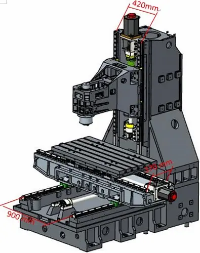
| X guide way span | 370 mm (14.5") |
| Y guide way span | 900 mm (35.4") |
| Z guide way span | 420 mm (16.5") |
| Tool | |
| Tool magazine capacity | 24T |
| Max diameter/length/weight of tool | Ø78mm/300mm/8kg |
| Tool change time | 1.8s |
| Others | |
| Power capacity | 35 kV A |
| Air pressure | 6-8bar |
| Machine dimension(L x W x H) | 4500x2650x3140mm |
| Net weight | 7500kg |
| Item 01 | Descriptions | |
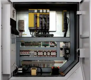
| 01.01 | FANUC 0i MF 5 Plus CNC system, 2MB system memory, 11/15 kW spindle motor | |
| 01.02 | 3 axis linear guide way | |
| 01.03 | 8000rpm belt drive spindle ,BT40 | |
| 01.04 | 24 tools arm type tools magazine | |
| 01.05 | Air conditioner of electrical cabinet | |
| 01.06 | Auto chip conveyer & chip chart | |
| 01.07 | Machine body washing system | |
| 01.08 | Auto oil lubrication system | |
| 01.09 | Tri-color light | |
| 01.10 | Air gun+ water gun | |
| 01.11 | Door lock switch | |
| 01.12 | Lighting lamp | |
| 01.13 | Full enclosure splash guard | |
| 01.14 | Telescopic covers |
| Item 02 | Description | Note |
| 02.01 | SIEMENS 828D 240 controller | 10 inch screen |
| 02.02 | SIEMENS 828D 260 controller | 10 inch screen |
| 02.03 | SIEMENS 828D 280 controller | 10 inch screen |
| SIEMENS with 15inch touch screen | Additional | |
| 02.04 | SHOP MILL | |
| 02.05 | FANUC OI MF 1 with βmotor | |
| 02.06 | FANUC OI MF1 with α motor | |
| AICC2 + NANO smoothing | Included in MF1 | |
| AICC2 400 block | Only available on MF1 | |
| Part program storage 2MB | Only available on MF1 | |
| G68.2 | Only available on MF1 | |
| MANUAL GUIDE I | Only available on MF1 | |
| 3-dimensional coordinate conversion | Only available on MF1 | |
| Data serve 2GB | Only available on MF1 | |
| FANUC 10 inch touch screen | ||
| FANUC 15 inch Non-touch screen | Only available on MF1 | |
| FANUC 15 inch Non-touch screen | Only available on MF1 | |
| 02.07 | MITSUBISHI M80B control | |
| 02.08 | MITSUBISHI M80A control | |
| 02.09 | HEIDENHAIN 620 | |
| 02.10 | Auto workpiece measurement , OMP60 | |
| 02.11 | Auto tool measurement RENISHAW, TS27R | |
| 02.12 | CTS preare | |
| 02.13 | CTS 20 bar | Belt 8000rpm spindle |
| 02.14 | CTS 30 bar | Belt 8000rpm spindle |
| 02.15 | CTS 70 bar | Belt 8000rpm spindle |
| 02.16 | M30 auto power off | |
| 02.17 | BBT40 | |
| 02.18 | SK 40 (long delivery time ) | |
| 02.19 | CAT 40 (long delivery time ) | |
| 02.20 | 3 AXIS linear scale | HEIDENHAIN |
| 02.21 | 3 axis roller guide way | |
| 02.22 | Z axis increase 250mm | Only height , not travel |
| 02.23 | Z axis increase 300mm | |
| 02.24 | 4TH AXIS INTERFACE | Included |
| 02.25 | magnetic chip conveyor | |
| 02.26 | Scraping chip conveyor for aluminums cutting | |
| 02.27 | Oil mister collector | |
| 02.28 | Rapid travel XY36m/min; Z 30m/min | |
| 02.29 | 30 tools magazine ,arm type | |
| 02.30 | Automatic tool break inspection | (must work with RENSHAW tools measure ) |
| 02.31 | Auto-door( pneumatic control ) | |
| 02.32 | 2 year FANUC warranty | |
| 02.33 | 2 year Siemens warranty | |
| 02.34 | 380V 50HZ/415V 50 HZ /220V 60 HZ | |
| 02.35 | Transformer | |
| 02.36 | Voltage stabilizer | |
| 02.37 | Remove tools magazine | |
| 02.38 | Remove chip conveyor | |
| 02.39 | Remove chips bucket | |
| 02.40 | Additional Hydraulic station | |
| 02.41 | Grease lubrication instead of oil | |
| 02.42 | Pulling stud | |
| 02.43 | Belt 10,000 rpm with oil cooler | |
| 02.44 | Direct 12000 with oil cooler, without CTS , | Siemens or FANUC |
| 02.45 | Direct 12000 , with CTS, FANUC | |
| 02.46 | Direct 12000K spindle with CTS 20 bar ,SIEMENS | 12000 + 3800,System +USD 1000,CTS unit +5000 only Siemens |
| 02.47 | Direct 15000, water cooler , with CTS, Siemens | |
| 02.48 | ZF gear box | |
| 02.49 | Increase spindle motor to 18/15KW beta motor | |
| 02.50 | BT40 8000 change to BT50 8000 | |
| 02.51 | BT40 8000 change to BT50 6000 | |
| 02.52 | Extend X travel to 1200mm | |
| 02.53 | CE standard | |
| 02.54 | Remove water gun | |
| 02.55 | Remove air conditioner for electrical cabinet |
| ● Standard ○ Optional X N/A | ||||
| NO. | Item | Spec. | TNC 620 | |
| 1 | Axes | Controlled axes | 3 axes | X, Y, Z |
| 2 | Additional Controlled axes | Max. 5 axes in total | ○ (Max. 5axes) | |
| 3 | Least command increment | 0.0001 mm (0.0001 inch), 0.0001° | ● | |
| 4 | Least input increment | 0.0001 mm (0.0001 inch), 0.0001° | ● | |
| 5 | MDI / DISPLAY unit | 19 "color flat-panel display, vertical, touch screen (for MC 8410) | ● | |
| 6 | Program memory for NC programs | 1.8GB | ||
| 7 | CFR CF memory card | 8GB | ||
| 8 | Commissioning and diagnostics | Data interfaces | Ethernet interface | ● |
| 9 | USB interface (USB 2.0) | ● | ||
| 10 | Machine functions | Look-ahead (Intelligent path control by calculating the path speed ahead of time) |
Max. 5000 blocks. | ● |
| 11 | User functions | Brief description | Basic version: 3 axes plus spindle | ● |
| 12 | One or two additional NC axes | ○ | ||
| 13 | Digital current and spindle speed control | ● | ||
| 14 | Program entry | HEIDENHAIN conversational and DIN/ ISO formats | ● | |
| 15 | Position data coordinates | Nominal positions for lines and arcs in Cartesian coordinates or polar coordinates | ● | |
| 16 | Incremental or absolute dimensions | ● | ||
| 17 | Display and input in mm or inches | ● | ||
| 18 | Tool compensation | Tool radius in the working plane and tool length | ● | |
| 19 | Radius-compensated contour look-ahead for up to 99 blocks (M120) | ○ | ||
| 20 | Three-dimensional tool-radius compensation for changing tool data without having to recalculate an existing program |
○ | ||
| 21 | Tool tables | Multiple tool tables with any number of tools | ● | |
| 22 | Constant contour speed | Relative to the path of the tool center | ● | |
| 23 | Relative to the tool’s cutting edge | ● | ||
| 24 | Parallel operation | Creating a program with graphical support while another program is being run | ● | |
| 25 | 3-D machining | Motion control with minimum jerk | ○ | |
| 26 | 3-D tool compensation through surface normal vectors | ○ | ||
| 27 | Keeping the tool normal to the contour | ○ | ||
| 28 | Tool radius compensation normal to the tool direction | ○ | ||
| 29 | Contour elements | Straight line | ● | |
| 30 | Chamfer | ● | ||
| 31 | Circular path | ● | ||
| 32 | Circle center point | ● | ||
| 33 | Circle radius | ● | ||
| 34 | Tangentially connecting circular arc | ● | ||
| 35 | Corner rounding | ● | ||
| 36 | Approaching and departing the contour | Via straight line: tangential or perpendicular | ● | |
| 37 | Via circular arc | ● | ||
| 38 | Program jumps | Subroutines | ● | |
| 39 | Program section repeats | ● | ||
| 40 | Calling any program as subroutine | ● | ||
| 41 | Coordinate transformation | Datum shift, rotation, mirror image, scaling factor (axis-specifi c) | ● | |
| 42 | Tilting the working plane, PLANE function | ○ | ||
| 43 | Actual position capture | Actual positions can be transferred directly into the NC program | ● | |
| 44 | Programming graphics | In the Programming and Editing mode, the contour of the NC blocks is drawn on screen while the blocks are being entered (2-D pencil-trace graphics), even while another program is running |
● | |
| 45 | Machining time | Calculation of machining time in the Test Run operating mode Display of the current machining time in the Program Run operating modes |
● | |
| 46 | Returning to the contour | Mid-program startup in any block in the program, returning the tool to the calculated nominal position to continue machining |
● | |
| 47 | Program interruption, leaving and returning to the contour | ● | ||
| 48 | Preset tables | One preset table for storing reference points | ● | |
| 49 | Datum tables | Several datum tables for storing workpiece-related datums | ● | |
| 50 | Parallel secondary axes | Compensating movement in the secondary axis U, V, W through the principal axis X, Y, Z | ● | |
| 51 | Including movements of parallel axes in the position display of the associated principal axis (sum display) | ● | ||
| 52 | Defi ning the principal and secondary axes in the NC program makes it possible to run programs on different machine confi gurations |
● | ||
| 53 | Conversational languages | English, Chinese (traditional, simplifi ed), Czech, Danish, Dutch, Finnish, French, German, Hungarian, Italian, Polish, Portuguese, Russian (Cyrillic), Spanish, Swedish |
● | |
| 54 | Fixed cycles | Drilling, conventional and rigid tapping, rectangular and circular pockets | ● | |
| 55 | Peck drilling, reaming, boring, counterboring, (centering) | ○ | ||
| 56 | Milling internal and external threads | ○ | ||
| 57 | Clearing level and oblique surfaces | ○ | ||
| 58 | Multioperation machining of straight and circular slots | ○ | ||
| 59 | Multioperation machining of rectangular and circular pockets | ○ | ||
| 60 | Linear and circular point patterns | ○ | ||
| 61 | Contour train, contour pocket—also with contour-parallel machining | ○ | ||
| 62 | OEM cycles (special cycles developed by the machine tool builder) can be integrated | ○ | ||
| 63 | Touch probe cycles | Touch probe calibration | ○ | |
| 64 | Compensation of workpiece misalignment, manual or automatic | ○ | ||
| 65 | Datum setting, manual or automatic | ○ | ||
| 66 | Automatic tool and workpiece measurement | ○ | ||
| ● Standard ○ Optional X N/A | ||||||
| No. | Item | Spec. | S828D | |||
| SW24x | SW26x | SW28x | ||||
| 1 | Controlled axis | Controlled axes | 3 axes | X, Y, Z | X, Y, Z | X, Y, Z |
| 2 | Additional controlled axes | 5 | 6+2 | 8+2 | ||
| 3 | Least command increment | 0.001mm (0.0001 inch) | ● | ● | ● | |
| 4 | Least input increment | 0.001mm (0.0001 inch) | ● | ● | ● | |
| 5 | Travel to fixed stop with Force Control | ○ | ○ | ○ | ||
| 6 | Interpolation & Feed Function | Reference point return | G75 FP=1 | ● | ● | ● |
| 7 | 2nd reference point return | G75 FP=2 | ● | ● | ● | |
| 8 | Inverse time feedrate | G93 | ● | ● | ● | |
| 9 | Helical interpolation | ● | ● | ● | ||
| 10 | Polynomial interpolation | X | X | X | ||
| 11 | Spline interpolation (A, B and C splines) | ○ | ○ | ○ | ||
| 12 | Separate path feed for corners and chamfers | ● | ● | ● | ||
| 13 | Acceleration with Jerk limitation | ● | ● | ● | ||
| 14 | Compressor for 3-axis machining | ● | ● | ● | ||
| 15 | Temperature compensation | ● | ● | ● | ||
| 16 | Look Ahead, recorded part program blocks: | Milling with MDynamics Advanced Surface | 150 | 300 | 450 | |
| 17 | Milling with MDynamics Top Surface | 600 | 600 | 600 | ||
| 18 | Look Ahead, IPO blocks, buffered: | Milling with MDynamics Advanced Surface | 50 | 100 | 150 | |
| 19 | Milling with MDynamics Top Surface | 200 | 200 | 200 | ||
| 20 | Cartesian point-to-point (PTP) travel | ● | ● | ● | ||
| 21 | TRANSMIT/cylinder surface transformation | ○ | ○ | ○ | ||
| 22 | Spindle Function | Tapping with compensating chuck/rigid tapping | ● | ● | ● | |
| 23 | Tool Function | Tool radius compensations in plane | ● | ● | ● | |
| 24 | Number of tools/cutting edges in tool list | 128/256 | 256/512 | 768/1536 | ||
| 25 | Tool length compensation | ● | ● | ● | ||
| 26 | Operation with tool management | ○ | ○ | ○ | ||
| 27 | Tool list | ● | ● | ● | ||
| 28 | Replacement tools for tool management | ○ | ○ | ○ | ||
| 29 | Monitoring of tool life and workpiece count | ● | ● | ● | ||
| 30 | Manual measurement of tool offset | ● | ● | ● | ||
| 31 | Magazine list | ● | ● | ● | ||
| 32 | Programming & Editing Function | Number of levels for skip blocks 2 | ● | ● | ● | |
| 33 | Number of levels for skip blocks 10 | ○ | ○ | ○ | ||
| 34 | Program/workpiece management | On additional plug-in CF card | ● | ● | ● | |
| 35 | On USB storage medium (e.g. disk drive, USB stick) | ● | ● | ● | ||
| 36 | On network drive | ○ | ○ | ○ | ||
| 37 | Program editor | Programming support for cycles program(Program Guide) | ● | ● | ● | |
| 38 | CNC editor with editing functions: select, copy, delete | ● | ● | ● | ||
| 39 | Programming graphics/free contour input (contour calculator) | ● | ● | ● | ||
| 40 | ShopMill Machining step programming | ○ | ○ | ○ | ||
| 41 | Technology cycles for drilling/milling | ● | ● | ● | ||
| 42 | Pocket milling free contour and islands stock removal cycle | ○ | ● | ● | ||
| 43 | Residual material detection | ○ | ○ | ○ | ||
| 44 | Access protection for cycles | ○ | ○ | ○ | ||
| 45 | Programming support can be extended, e.g. customer cycles | ● | ● | ● | ||
| 46 | 2D simulation | ● | ● | ● | ||
| 47 | 3D simulation, finished part | ○ | ○ | ○ | ||
| 48 | OTHERS FUNCTIONS (Operation, setting & Display, etc) |
Switchover: inch/metric | ● | ● | ● | |
| 49 | Manual measurement of zero/work offset | ● | ● | ● | ||
| 50 | Automatic tool/workpiece measurement | ● | ● | ● | ||
| 51 | Reference point approach, automatic/via CNC program | ● | ● | ● | ||
| 52 | Execution from USB or CF card interface on operator panel front | ● | ● | ● | ||
| 53 | Execution from network drive | ○ | ○ | ○ | ||
| 54 | 10.4" color display | ● | ● | ● | ||
| 55 | 15.0" color display | ○ | ○ | ○ | ||
| 56 | Alarms and messages | ● | ● | ● | ||
| 57 | Automatic measuring cycles | ○ | ○ | ○ | ||
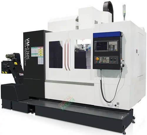
The VM1260S Vertical Machining Center by Fortune Pacific is a high-performance CNC milling machine designed for precision machining of complex parts. This robust 3-axis vertical machining center features a rigid cast iron construction, linear guideways, and a high-speed spindle (8000 rpm) for superior accuracy and surface finish. Key specifications include 1200x600x600mm XYZ travels, 24m/min rapid traverse, and 0.005mm positioning repeatability. The machine comes standard with a 16+1 tool automatic changer, FANUC 0i-MF control system, and flood coolant system. Ideal for aerospace components, automotive parts, mold/die making, and general precision engineering applications. Operators praise its vibration-dampening structure, thermal stability, and energy-efficient servo motors that reduce operating costs. The optimized machine layout provides excellent chip evacuation and easy maintenance access.
Вертикальный обрабатывающий центр VM1260S от Fortune Pacific - это прецизионный станок для 3D-фрезерования сложных деталей с ЧПУ. Станок с жесткой чугунной станиной и линейными направляющими обеспечивает точность позиционирования 0.005 мм. Основные характеристики: ход по осям XYZ 1200×600×600 мм, скорость подачи 24 м/мин, шпиндель 8000 об/мин. Комплектуется автоматическим сменщиком инструмента на 16+1 позиций, системой ЧПУ FANUC 0i-MF и системой подачи СОЖ. Широко применяется в авиакосмической отрасли, автомобилестроении, производстве пресс-форм. Ключевые преимущества: виброустойчивая конструкция, термокомпенсированные узлы, энергоэффективные сервоприводы. Оптимальная компоновка обеспечивает удобство обслуживания и эффективное удаление стружки.
El centro de mecanizado vertical VM1260S de Fortune Pacific es una máquina herramienta CNC de alto rendimiento para fresado de precisión. Con estructura de hierro fundido y guías lineales, ofrece repetitividad de 0.005mm y velocidades de avance rápido de 24m/min. Características principales: carrera XYZ 1200x600x600mm, husillo de 8000rpm, cambiador automático de herramientas 16+1, control FANUC 0i-MF. Perfecto para fabricación de moldes, componentes aeroespaciales y piezas automotrices. Ventajas clave: diseño antivibratorio, motores servo energéticamente eficientes, excelente evacuación de virutas. La máquina incluye bomba de refrigerante y sistema de lubricación centralizado para máxima productividad.
O centro de usinagem vertical VM1260S da Fortune Pacific é uma máquina CNC de alta precisão para fresagem 3D de componentes complexos. Com estrutura rígida em ferro fundido e guias lineares, atinge repetibilidade de posicionamento de 0.005mm. Principais parâmetros: curso XYZ 1200×600×600mm, velocidade rápida 24m/min, eixo árvore 8000rpm. Equipamento padrão inclui trocador automático de ferramentas 16+1, controle FANUC 0i-MF e sistema de refrigeração. Aplicações ideais: moldes, matrizes, componentes automotivos e aeroespaciais. Destaques: construção anti-vibração, alta estabilidade térmica, baixo consumo energético e fácil manutenção.
Mesin bubut vertikal CNC VM1260S dari Fortune Pacific adalah pusat permesinan presisi tinggi untuk komponen industri. Spesifikasi utama: area kerja 1200x600x600mm, kecepatan spindle 8000rpm, akurasi 0.005mm. Dilengkapi dengan pengganti alat otomatis 16+1, sistem kontrol FANUC 0i-MF, dan pendingin cairan. Cocok untuk pembuatan mold, komponen otomotif, dan part aeroangkasa. Keunggulan: konstruksi anti getar, motor servo hemat energi, sistem pembuangan chip efisien. Desain kokoh dengan bahan besi cor memberikan stabilitas tinggi selama operasi berat.
مرکز ماشینکاری عمودی VM1260S شرکت فورچون پسیفیک یک دستگاه فرز CNC با دقت بالا برای تولید قطعات صنعتی پیچیده است. مشخصات فنی: محدوده کاری 1200x600x600mm، سرعت اسپیندل 8000 دور در دقیقه، دقت موقعیت یابی 0.005mm. مجهز به سیستم تعویض ابزار خودکار 16+1، کنترلر FANUC 0i-MF و سیستم خنک کاری. کاربردهای اصلی: قالب سازی، قطعات خودرو و صنایع هوایی. مزایا: ساختار ضد ارتعاش، موتورهای سروو کم مصرف، طراحی بهینه برای تخلیه براده. این دستگاه با بدنه چدنی سنگین از پایداری فوق العاده ای در شرایط کاری سخت برخوردار است.
Máy gia công đứng VM1260S của Fortune Pacific là trung tâm gia công CNC chính xác cao cho chi tiết máy phức tạp. Thông số kỹ thuật: hành trình XYZ 1200x600x600mm, tốc độ trục chính 8000 vòng/phút, độ chính xác 0.005mm. Trang bị bộ đổi dao tự động 16+1, hệ điều khiển FANUC 0i-MF và hệ thống làm mát. Ứng dụng: khuôn mẫu, chi tiết ô tô, linh kiện hàng không. Ưu điểm: kết cấu giảm rung, động cơ servo tiết kiệm điện, hệ thống thoát phoi hiệu quả. Máy có khung đúc gang nặng đảm bảo độ ổn định cao khi gia công tải trọng lớn.
เครื่องกัดแนวตั้ง VM1260S จาก Fortune Pacific เป็นเครื่องจักร CNC ความแม่นยำสูงสำหรับชิ้นส่วนอุตสาหกรรม ข้อมูลจำเพาะ: พื้นที่ทำงาน 1200x600x600mm, ความเร็วสปินเดิล 8000 รอบ/นาที, ความแม่นยำ 0.005mm. มาพร้อมระบบเปลี่ยนมีดอัตโนมัติ 16+1 ตัว, ระบบควบคุม FANUC 0i-MF และระบบหล่อเย็น เหมาะสำหรับการผลิตแม่พิมพ์, ชิ้นส่วนยานยนต์ และอะไหล่การบิน ข้อดี: โครงสร้างลดการสั่นสะเทือน, มอเตอร์เซอร์โวประหยัดพลังงาน, การออกแบบที่ดีสำหรับการกำจัดเศษตัด เครื่องมีโครงสร้างเหล็กหล่อหนาทำให้มีความมั่นคงสูงเมื่อทำงานกับชิ้นงานขนาดใหญ่
Mesin pengilangan menegak VM1260S dari Fortune Pacific ialah pusat pemesinan CNC ketepatan tinggi untuk komponen industri. Spesifikasi utama: julat kerja 1200x600x600mm, kelajuan spindle 8000rpm, ketepatan 0.005mm. Dilengkapi dengan penukar alat automatik 16+1, sistem kawalan FANUC 0i-MF dan sistem penyejuk. Sesuai untuk pembuatan acuan, komponen automotif dan aeroangkasa. Kelebihan: struktur anti-getaran, motor servo menjimatkan tenaga, reka bentuk optimum untuk pembuangan serpihan. Mesin mempunyai rangka besi tuang berat yang memberikan kestabilan unggul semasa operasi beban tinggi.
O centro de usinagem vertical VM1260S da Fortune Pacific é uma máquina de alta performance projetada para operações de fresagem precisas. Equipado com um fuso de alta velocidade e sistema de controle CNC avançado, este centro de usinagem é ideal para aplicações em moldes, matrizes e peças mecânicas complexas. Com mesa de trabalho robusta e curso longo (X/Y/Z: 1200/600/600mm), oferece excelente estabilidade e precisão (±0.005mm). A estrutura em aço fundido com amortecimento de vibrações garante durabilidade, enquanto o trocador automático de ferramentas (24 posições) aumenta a produtividade. Principais configurações incluem sistema de refrigeração, luz de trabalho LED e interface homem-máquina intuitiva. Muito procurado por oficinas mecânicas e indústrias aeronáuticas por sua relação custo-benefício e baixa manutenção.
Ang VM1260S Vertical Machining Center mula sa Fortune Pacific ay isang high-precision CNC machine na perpekto para sa paggawa ng mga komplikadong bahagi ng makina. Kilala rin bilang "vertical mill" o "CNC milling machine", ang makina ay may malakas na spindle (10,000rpm) at matatag na structure para sa heavy-duty machining. Ang malaking worktable (1200x600mm) ay nag-aaccommodate ng malalaking workpiece, habang ang automatic tool changer (24 tools) ay nagpapabilis sa production process. Ginagamit ito sa automotive, aerospace, at mold manufacturing industries dahil sa mataas nitong accuracy (±0.005mm) at repeatability. Key features: rigid box-way construction, Mitsubishi CNC system, at energy-efficient design. Perfect para sa mga machine shop na naghahanap ng reliable at cost-effective na machining solution.
Il centro di lavorazione verticale VM1260S rappresenta l'eccellenza nel campo delle macchine utensili CNC. Dotato di un mandrino potente (10.000 giri/min) e controllo numerico Mitsubishi, questa fresatrice verticale offre precisione micronetrica (±0,005mm) per lavorazioni su metalli duri e leghe speciali. La struttura a colonna fissa con guide a cassetto garantisce rigidità durante le operazioni di sgrossatura e finitura. Configurazioni opzionali includono: sistema di misura tool breakage, refrigerante attraverso mandrino e fourth axis rotary table. Ideale per officine meccaniche specializzate in stampi e prototipazione rapida, combina alta produtività (24 utensili ATC) con facilità di programmazione. Termini chiave nel settore: "fresatrice CNC professionale", "centro di lavoro per metalli", "macchina utensile ad alta velocità".
Fortune Pacific'ın VM1260S Dikey İşleme Merkezi, yüksek hassasiyetli CNC frezeleme işlemleri için tasarlanmış endüstriyel sınıf bir makinedir. "CNC dik işlemci" veya "endüstriyel freze" olarak da bilinen bu ekipman, 1200x600x600mm çalışma hacmiyle büyük parçaların işlenmesine olanak tanır. Temel özellikler: 24 takımlı otomatik takım değiştirici, 10.000 dev/dak spindle hızı ve ±0.005mm işleme hassasiyeti. Sektörde aranan diğer özellikler: "sert metal işleme kapasitesi", "enerji verimliliği", "kullanıcı dostu arayüz". Otomotiv yedek parça, kalıpçılık ve havacılık sektörlerinde tercih edilen bu makine, dayanıklı döküm gövde yapısıyla uzun ömürlü kullanım sunar.
Le centre d'usinage vertical VM1260S de Fortune Pacific est une solution complète pour l'usinage de précision. Appelé aussi "fraiseuse CNC verticale" ou "centre d'usinage à portique", cette machine-outil professionnelle dispose d'une table de 1200x600mm avec charge admissible de 800kg. La broche 10.000tr/min refroidie par air assure des finitions de qualité même sur les aciers trempés. Options disponibles: palpeur 3D, système de lubrification centralisé et commande numérique Mitsubishi M80. Particulièrement adapté à la fabrication de moules et matrices, ce centre d'usinage se distingue par sa productivité (changement d'outil en 2s) et sa facilité de programmation. Terminologie métier: "usinage haute vitesse", "fraisage 5 axes", "machine-outil rigide".
مركز التشغيل العمودي VM1260S من Fortune Pacific هو آلة CNC متعددة الوظائف مصممة للأعمال الدقيقة. تعرف في السوق بـ"الفريزة العمودية" أو "ماكنة CNC للمعادن"، تتميز بمنطقة عمل كبيرة (1200x600x600 مم) ودقة تصل إلى ±0.005 مم. المكونات الرئيسية: رأس دوار بقدرة 10,000 دورة/دقيقة، نظام تحكم Mitsubishi، ومجلة أدوات أوتوماتيكية (24 أداة). تستخدم على نطاق واسع في صناعة القوالب وقطع غيار السيارات والأجزاء الصناعية الدقيقة. ميزات رئيسية: هيكل من الحديد الزهر يقلل الاهتزازات، استهلاك طاقة منخفض، وشاشة تحكم سهلة الاستخدام. مصطلحات تقنية شائعة: "ماكينات تشغيل المعادن"، "مراكز تصنيع CNC"، "آلات خراطة وفريزة".
Die VM1260S Vertikal-Bearbeitungszentrum von Fortune Pacific ist eine Hochleistungs-CNC-Fräsmaschine für die präzise Metallbearbeitung. Als "CNC-Fräse" oder "Bearbeitungszentrum" bekannt, bietet diese Maschine herausragende Leistung mit 10.000 U/min Spindeldrehzahl und ±0,005mm Positioniergenauigkeit. Wichtige Konfigurationen: 24-Werkzeugmagazin, Kühlmittelsystem und LED-Arbeitsleuchte. Die stabile Gussbauweise mit Führungsschienen macht sie ideal für die Zerspanung von Stahl, Titan und Leichtmetallen. Anwendungen: Formenbau, Luftfahrtteile und Präzisionsmechanik. Branchenbegriffe: "Werkzeugmaschinen", "Spanende Bearbeitung", "Fertigungsautomatisierung". Besonderheiten: energieeffizient, wartungsarm und mit moderner Steuerungstechnik.
Het VM1260S verticaal bewerkingscentrum van Fortune Pacific is een veelzijdige CNC-freesmachine voor precisiebewerkingen. In de industrie ook bekend als "CNC frees" of "bewerkingsmachine", beschikt dit model over een groot werkbereik (1200x600x600mm) en automatische gereedschapswisselaar (24 posities). Kernspecificaties: 10.000 omw/min spil, Mitsubishi besturingssysteem en ±0.005mm positioneringsnauwkeurigheid. Geschikt voor hardmetaalbewerking, matrijzenproductie en complexe componenten. Belangrijke termen: "metaalbewerkingsmachines", "industriële freesapparatuur", "hoogproductieve CNC". Pluspunten: robuust gietijzeren frame, energiezuinige aandrijving en gebruiksvriendelijke interface.
Centrum obróbcze pionowe VM1260S od Fortune Pacific to zaawansowana maszyna CNC do precyzyjnej obróbki metali. Znane również jako "frezarka CNC" lub "obrabiarka pionowa", urządzenie oferuje obszar roboczy 1200x600mm i dokładność pozycjonowania ±0,005mm. Główne komponenty: wrzeciono 10.000 obr/min, system sterowania Mitsubishi i automatyczny zmieniacz narzędzi (24 miejsca). Idealne do produkcji form wtryskowych, części lotniczych i elementów precyzyjnych. Zalety: sztywna konstrukcja z żeliwa, niskie koszty eksploatacji i łatwa obsługa. Branżowe określenia: "obróbka skrawaniem", "maszyny do metalu", "nowoczesne frezarki CNC". Dodatkowe opcje: czwarta oś obrotowa i system pomiarowy.
Centrul de prelucrare vertical VM1260S de la Fortune Pacific este o mașină CNC de înaltă precizie pentru frezarea metalelor. Cunoscut și sub denumirea de "freză CNC verticală", acest echipament industrial oferă o suprafață de lucru generoasă (1200x600mm) și viteză spindle de 10.000 rpm. Configurații standard: schimbător automat de scule (24 poziții), sistem de răcire și control numeric Mitsubishi. Aplicatii principale: fabricarea matrițelor, piese auto și componente aerospațiale. Termeni tehnici relevanți: "mașini-unelte CNC", "centru de prelucrare", "frezare de precizie". Avantaje: construcție robustă din fontă, precizie ±0,005mm și interfață operator intuitivă. Opțional: sistem de detectare a ruperii sculei și rotativă a 4-a axă.
A Fortune Pacific VM1260S vertikális megmunkáló központ a precíziós megmunkálás csúcstechnológiáját képviseli. Ez a 3-tengelyes CNC marógép kiválóan alkalmas összetett alkatrészek gyártására acél, ötvözet, alumínium és kompozit anyagokból. A gép fő jellemzői közé tartozik a nagy nyomatékú szervomotor, lineáris vezetőrendszer a kiváló pontosságért, és egy robusztus öntöttvas konstrukció a minimális rezgések érdekében. A 12,000 rpm-es orsó, 30-es eszköztár és a 1200x600x600 mm-es munkatér ideális megoldást kínál a repülőgép-iparban, autóiparban és formagyártásban dolgozó vállalkozások számára. A gépet intelligens hűtőrendszerrel, automatizált eszközválasztóval és felhasználóbarát Fanuc vezérlőrendszerrel szerelik. Különösen népszerű a "CNC marócenter", "vertikális marógép" és "ipari megmunkáló központ" kifejezésekkel keresők körében.
Το κατακόρυφο κέντρο επεξεργασίας VM1260S της Fortune Pacific είναι μια κορυφαία λύση για βιομηχανική κατεργασία μεγάλης ακρίβειας. Αυτό το CNC μηχάνημα με τρεις άξονες διαθέτει ισχυρό σπειροειδές σύστημα ψύξης, αυτόματο εργαλειοθήκη 30 θέσεων και ευρύ χώρο εργασίας 1200x600x600 mm. Ο κεντρικός άξονας 12.000 rpm με υψηλή ροπή εξασφαλίζει άψογη απόδοση στην επεξεργασία χάλυβα, κραμάτων και σύνθετων υλικών. Η μηχανή χρησιμοποιεί γραμμικούς οδηγούς για ακριβή κίνηση και προηγμένο σύστημα Fanuc CNC για εύκολο προγραμματισμό. Δημοφιλής σε βιομηχανίες όπως η αεροδιαστημική, η αυτοκινητοβιομηχανία και η κατασκευή καλουπιών, το VM1260S αναφέρεται συχνά ως "βιομηχανικό CNC", "κατακόρυφο κέντρο κατεργασίας" ή "αυτοματοποιημένο κέντρο μηχανουργικής". Η δομή από χυτοσίδηρο ελαχιστοποιεί τις δονήσεις για υψηλή επιπεδότητα επιφανειών.
Vertikální obráběcí centrum Fortune Pacific VM1260S představuje špičkové řešení pro přesné obrábění kovů. Tento 3osý CNC stroj kombinuje vysokorychlostní vřeteno 12 000 ot/min s robustní litinovou konstrukcí pro maximální stabilitu. Stroje s označením "vertikální frézovací centrum" nebo "průmyslové CNC" jsou vyhledávány pro výrobu forem, leteckých komponentů a automobilových dílů. Konfigurace zahrnuje lineární vedení, 30nástrojový automatický měnič a pracovní prostor 1200×600×600 mm. Mezi klíčové parametry patří posuv 48 m/min, rozlišení 0,001 mm a Fanuc ovládací systém. Uživatelé oceňují nízké provozní náklady, energetickou účinnost a možnost integrace do robotizovaných linek. Speciální aplikace zahrnují obrábění titanu, hliníkových slitin a kompozitních materiálů.
Вертикалният обработващ център VM1260S от Fortune Pacific е върхово решение за прецизна обработка на метали. Този 3-осен CNC фрезов машина се отличава с високоскоростно шпиндел 12 000 об/мин, автоматична смяна на инструменти с 30 позиции и работна зона 1200x600x600 mm. Машината се използва широко в авиационната, автомобилна и формова промишленост. Ключови характеристики включват Fanuc управление, линеарни водачи за висока точност и здрава чугунена конструкция. Сред търсещите такива машини са популярни термини като "CNC фреза", "вертикален фрезовачен център" и "промишлен металорежещ стан". Специалните конфигурации включват охлаждане чрез мист, изсмукване на стружки и лазерни измервателни системи. Прецизността до 0,005 mm и високата производителност го правят идеален за серийно производство.
Fortune Pacific VM1260S вертикални обрадни центар представља врхунско решење за прецизну обраду метала. Овај 3-осни CNC апарат са 12.000 обртаја у минути и аутоматском променом алатки идеалан је за авио-индустрију, производњу алата и аутомобилску индустрију. Кључне предности укључују Фанук контролни систем, линеарне водиче за прецизно позиционирање и радни простор од 1200x600x600 mm. Популарни претраживани изрази за овај тип машина су "CNC глодалица", "вертикални глодали центар" и "индустријски обрадни центар". Машина поседује јаку конструкцију од ливеног гвожђа за смањење вибрација и побољшану тачност. Додатне опције укључују систему за хлађење, аутоматско пуњење алатки и софтвер за симулацију процеса обраде. Посебно је погодан за обраду челика, алуминијума и композитних материјала.
Vertikálne obrábacie centrum VM1260S od Fortune Pacific je špičkové CNC obrábacie zariadenie pre presnú obrábku kovov. Tento 3-osý stroj s vretenom 12 000 ot./min. a automatickou výmenou nástrojov je ideálny pre letecký priemysel, výrobu foriem a automobilový priemysel. Hlavné výhody zahŕňajú Fanuc riadiaci systém, lineárne vedenie pre vysokú presnosť a pracovný priestor 1200x600x600 mm. Medzi často vyhľadávané výrazy patria "CNC fréza", "vertikálne obrábacie centrum" a "priemyselné obrábacie stredisko". Stroje tohto typu sa vyznačujú nízkymi prevádzkovými nákladmi, vysokou spoľahlivosťou a možnosťou integrácie do automatizovaných výrobných liniek. Špeciálne aplikácie zahŕňajú obrábanie titánu, hliníkových zliatin a kompozitných materiálov s vysokou presnosťou do 0,005 mm.
Vertikalni obradni centar VM1260S tvrtke Fortune Pacific vrhunsko je rješenje za preciznu obradu metala. Ovaj 3-osni CNC stroj s 12.000 okretaja u minuti i automatskom izmjenom alata idealan je za zrakoplovnu industriju, izradu alata i automobilsku industriju. Ključne prednosti uključuju Fanuc upravljački sustav, linearna vodilja za precizno pozicioniranje i radni prostor od 1200x600x600 mm. Popularni izrazi za pretraživanje uključuju "CNC glodalica", "vertikalni glodalni centar" i "industrijski obradni centar". Strojevi ovog tipa posebno su pogodni za obradu čelika, aluminija i kompozitnih materijala s visokom preciznošću do 0,005 mm. Posebne konfiguracije uključuju sustav hlađenja, automatsko punjenje alata i softver za simulaciju procesa obrade.
Vertikalno obdelovalno središče VM1260S podjetja Fortune Pacific je vrhunska rešitev za natančno obdelavo kovin. Ta 3-osni CNC stroj z vretenom 12.000 vrt/min in samodejnim menjalnikom orodja je idealen za letalsko industrijo, izdelavo orodij in avtomobilsko industrijo. Glavne prednosti vključujejo Fanuc krmilni sistem, linearne vodilne za natančno pozicioniranje in delovni prostor 1200x600x600 mm. Priljubljeni iskalni izrazi vključujejo "CNC rezalni stroj", "vertikalno rezalno središče" in "industrijsko obdelovalno središče". Posebne konfiguracije vključujejo sistem za hlajenje, laserski merilni sistem in možnost integracije v robotske linije. Stroji te vrste so posebej primerni za obdelavo jekla, aluminija in kompozitnih materialov z visoko natančnostjo do 0,005 mm.
Вертикальний обробний центр Fortune Pacific VM1260S - це високотехнологічне рішення для прецизійної обробки металів. Цей 3-х осьовий верстат з ЧПУ має шпиндель 12 000 об/хв, автоматичну зміну інструментів (30 позицій) та робочу зону 1200×600×600 мм. Ключові переваги включають систему керування Fanuc, лінійні напрямні для високої точності та міцну чавунну конструкцію. Популярні запити серед покупців: "фрезерний верстат з ЧПУ", "вертикальний обробний центр" та "промисловий ЧПУ верстат". Особливо ефективний при обробці алюмінію, титану та інших важкооброблюваних матеріалів. Додаткові опції включають систему охолодження, видалення стружки та програмне забезпечення для 3D моделювання. Точність позиціювання до 0,005 мм робить його ідеальним для виробництва прецизійних деталей в авіаційній та автомобільній промисловості.