| Main parameters | Unit | UCG630 |
|---|---|---|
| Distance between centers | mm | 2000; 3000; 4000; 5000 (79”; 118”; 157”; 197”) |
| Center height | mm | 370 (15”) |
| Dia. Ground(O.D) | mm | Φ30~630 (1.2-25”) |
| Dia. Ground(I.D) | mm | Φ30~200 (1.2-7.9”) |
| Max length ground(O.D) | mm | 2000; 3000; 4000; 5000 (79”; 118”; 157”; 197”) |
| Max length ground(I.D) | mm | 320 (13”) |
| Max weight of workpiece | kg | 3000 |
| Workhead swiveling angle | ° | +90° |
| Workhead center taper | MT-6 | |
| Workhead spindle speed | r/min | 50HZ: 14~140 stepless |
| Wheel spindle speed | r/min | 1100/550 |
| Wheelhead rapid travel | mm | 100 (3.9”) |
| Wheelhead max travel | mm | 450 (18”) |
| Wheelhead swiveling angle | ° | ±30º |
| Wheelhead hand feed per. rev | mm | Rough:4; Fine: 0.5 |
| Wheelhead hand feed per. gra | mm | Rough:0.02; Fine: 0.0025 |
| Wheel size( OD x W x ID) | mm | Φ600x75x305 (24x3x12”) |
| Peripheral velocity | m/s | 35/17.5 |
| Internal grinding device spindle speed | r/min | 10000 |
| Dimension of internal grinding wheel | mm | Max:175x32x32 (6.9x1.3x1.3”); Min: 30x25x10 (1.2x1x0.4”) |
| Table hand feed per. rev | mm | 5 |
| Max swiveling angle of table: Clockwise | ° | 3°(2000); 1°(3000; 4000; 5000) |
| Max swiveling angle of table: Anticlockwise | ° | 4°(2000); 3°(3000); 2.5°(4000); 1.5°(5000) |
| Longitudinal speed range of table | m/min | 0.1~2.5 |
| Tailstock center tape | Metric 80 | |
| Tailstock quill travel | mm | 70 (2.8”) |
| Wheelhead motor power | kW | 7/11 |
| Internal grinding device motor power | kW | 1.5 |
| Workhead motor power | kW | 15 |
| Gross weight | kg | 20000(2000); 22000(3000); 24000(4000); 26000(5000) |
| Packing size(L x W x H) | mm | 6950x2230x2260(2000); 8900x2230x2260(3000) 11000x2230x2260(4000); Disperse pack L:12500(5000) |
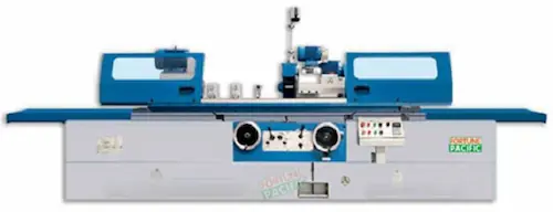
A világvezető UCG630 univerzális hengercsiszoló gépet kínáljuk, amely kivételes pontosságot és megbízhatóságot nyújt nehézipari alkalmazásokhoz. Ez a gépi megoldás hidraulikus orsóvezérléssel, automatikus keresztbeállítással és digitális mérőrendszerrel rendelkezik. Legfontosabb paraméterek: 630mm maratott hossz, 250mm maratott átmérő, 800kg megengedett terhelés. Fő komponensek: extra merev alapadag, precíziós orsóegység, CNC vezérlőrendszer. Alkalmazás: tengelyek, perselyek, formaszerszámok gyártására. Előnyök: 0,001mm-es pontosság, kopásálló vezetőfelületek, energiatakarékos hajtás. Keresési kifejezések: precíziós hengerlő gép, csiszológép árak, ipari megmunkáló berendezések, nagy pontosságú felületi megmunkálás, marógépek forgalmazó, megbízható hengercsiszolás.
Το Fortune Pacific παρουσιάζει το UCG630 Καθολικό Κυλινδρικό Εργαλειομηχανή λείανσης - κορυφαία λύση για ακραία ακρίβεια (0.001mm) στη βιομηχανία. Βασικά χαρακτηριστικά: μέγιστο μήκος λείανσης 630mm, διάμετρος λείανσης 250mm, φορτίο τραπεζιού 800kg. Περιλαμβάνει αυτόματο υδραυλικό σύστημα προσαρμογής, ψηφιακό σύστημα μέτρησης και CNC έλεγχο. Εφαρμογές: κατασκευή αξόνων, δακτυλίων κινητήρων, εργαλείων καλουπιών. Πλεονεκτήματα: αυξημένη παραγωγικότητα έως 40%, εξαιρετική σταθερότητα λόγω βαρέος χυτοσιδήρου, ενεργειακά αποδοτικός κινητήρας. Συνώνυμα: μηχανή ακριβείας λείανσης, βιομηχανικό εργαλειομηχανή, εξειδικευμένο μηχάνημα μεταλλουργίας. Λέξεις κλειδιά: μηχανή ακριβείας λείανσης, βιομηχανική λείανση μετάλλων, CNC κυλινδρική λείανση, εξοπλισμός μηχανουργικής, υψηλής απόδοσης λείανση.
Univerzální bruska UCG630 od Fortune Pacific představuje špičkové řešení pro přesné válcové broušení s tolerancí 0,001mm. Technické parametry: max. brousicí délka 630mm, průměr broušení 250mm, nosnost stolu 800kg. Klíčové komponenty: vysoce tuhá litinová konstrukce, přesné vřeteno s hydrostatickými ložisky, digitální měřící systém. Aplikace: výroba hřídelí, pístů, forem. Hlavní výhody: automatické posuvy, energeticky úsporný provoz, minimální vibrace. Synonyma: bruska na válec, přesná bruska kovů, CNC brusný stroj. Dlouhá slova: průmyslové brusky na kovy, vysoce přesné broušení hřídelí, automatizované brusné stroje. Výrazy: "ostrá jako břitva" povrch, "železná" spolehlivost, blesková kalibrace.
Фортун Пасифик предлага UCG630 Универсален Цилиндричен Шлайфмашин с безкомпромисна точност (0.001mm). Основни параметри: шлайфовална дължина 630mm, диаметър 250mm, товароподемност на масата 800kg. Ключови компоненти: суперздрава основа, високоточни шпиндели, ЧПУ управление. Приложения: производство на валове, втулки, инструментални форми. Предимства: автоматични хидравлични регулировки, енергийна ефективност, изключителна стабилност. Търсещи фрази: високоточни шлайфа, индустриални металообработващи машини, автоматизирано шлайфане. Жаргон: "лазерна" точност, "танкова" издръжливост, бърза настройка. Дълги ключови думи: професионални машини за цилиндрично шлайфане, шлайфовки за автомобилна индустрия.
Fortune Pacific нуди UCG630 Универзалну Цилиндричну Брусилицу за прецизно глaчање (0.001mm). Главни параметри: дужина глaчења 630mm, пречник 250mm, носивост стола 800kg. Кључни делови: крута конструкција, прецизни вратила, CNC управљање. Примена: производња осовина, лежишта, алата. Предности: аутоматско подешавање, смањена потрошња енергије, дуг век трајања. Синоними: прецизна брусилица, индустријска машина за обраду метала. Изрази: "бријaчa" оштрина, "неуништивa" поузданост. Кључне фразе: аутоматизоване брусилице за метале, високопрецизно глaчање осовина, робусне индустријске брусилице.
Univerzálna brúska UCG630 od Fortunepacific poskytuje extrémnu presnosť (0,001mm) pri valcovom brúsení. Parametre: max. dĺžka brúsenia 630mm, priemer 250mm, nosnosť stola 800kg. Konštrukcia: ťažká liatinová základňa, presné vretená s hydrostatickými ložiskami. Výhody: automatické posuvy, nízkohlučný prevádzka, dlhá životnosť. Použitie: brúsenie hriadeľov, puzdier, formovacích nástrojov. Hľadané výrazy: presné brúsky kovov, CNC brúsne stroje, priemyselné brúsenie. Odborný slang: "hodinárska" presnosť, "nemec" spoľahlivosť. Dlhé frázy: vysoko výkonné brúsne stroje pre automobilový priemysl.
Universalni brusni stroj UCG630 tvrtke Fortunepacific nudi vrhunsku preciznost (0.001mm) za cilindrično brušenje. Tehnički parametri: max. duljina brušenja 630mm, promjer 250mm, nosivost stola 800kg. Ključne komponente: kruta građa, precizna vretena, CNC upravljanje. Primjena: proizvodnja vratila, čahura, alata. Prednosti: automatsko podešavanje, niska potrošnja energije, iznimna stabilnost. Sinonimi: precizna brusilica, industrijski stroj za obradu metala. Fraze: "britka" preciznost, "gvozdena" pouzdanost. Ključne riječi: automatizirani strojevi za brušenje metala.
Univerzalni brusilni stroj UCG630 podjetja Fortunepacific zagotavlja izjemno natančnost (0,001 mm) za valjasto brušenje. Specifikacije: največja dolžina brušenja 630 mm, premer 250 mm, nosilnost mize 800 kg. Glavne komponente: togo ogrodje, visoko natančna vretena, CNC krmiljenje. Prednosti: avtomatsko nastavljanje, zmanjšana vibracija, energijska učinkovitost. Uporaba: brušenje gredi, puš, orodij. Iskalni izrazi: natančni brusilni stroji, CNC stroji za brušenje, industrijska obdelava kovin. Fraze: "britva" ostra natančnost, "kamnita" zanesljivost. Ključne besede: visoko zmogljivi brusilni stroji za avtomobilsko industrijo.
Фортун Пасіфик пропонує Універсальний круглошліфувальний верстат UCG630 для надточного шліфування (0.001мм). Основні параметри: довжина шліфування 630мм, діаметр 250мм, вантажопідйомність столу 800кг. Ключові компоненти: жорстка станина, прецизійні шпінделі, ЧПУ керування. Застосування: обробка валів, втулок, прес-форм. Переваги: автоматичне регулювання, знижена вібрація, енергоощадність. Пошукові фрази: прецизійні шліфувальні верстати, промислове шліфування металів, ЧПУ верстати для циліндричного шліфування. Жаргон: "лазерна" точність, "незламна" надійність. Довгі ключові слова: високопродуктивні шліфувальні верстати для авіаційної промисловості.