| Model | UCG200 | UCG320 | |
|---|---|---|---|
| Type | PSA | PSA | |
| Distance between centers mm | 520; 765; 1080 (20”; 30”; 43”) |
520; 765; 1080 (20”; 30”; 43”) |
|
| Center height mm | 125 (4.9”) | 180 (7.1”) | |
| Max. swiveling diameter mm | Φ240 (9.4”) | Φ350 (13.8”) | |
| Max. grinding length mm | 500; 750; 1000 (20”; 30”; 39”) |
500; 750; 1000 (20”; 30”; 39”) |
|
| External grinding range mm | Φ5~200 (2-7.9”) | Φ5~320 (2-13”) | |
| Internal grinding range mm | Φ13~80 (0.51-3.1”) | Φ16~125 (0.63-4.9”) | |
| Distance between workpiece center to ground mm | 1000 (39”) | 1050 (41”) | |
| Internal grinding length mm | 125 (4.9”) | 160 (6.3”) | |
| Max. weight of workpiece between centers kg | 50 | 100 | |
| Max. weight of workpiece in chuck kg | 30 | 30 | |
| Grinding wheel | Dimensions (OD × W × ID) mm | Φ400×(32~50)×203 (16x(1.3-2)x8”) |
Φ400×(32~50)×203 (16x(1.3-2)x8”) |
| Max. linear velocity m/s | 35 | 35 | |
| Internal grinding (OD x W) mm | Φ50x32 (2x1.3”) | Φ50x32 (2x1.3”) | |
| Swiveling angle of table | Clockwise | 9°(500); 8°(750); 3° (1000) | 9°(500); 8°(750); 3° (1000) |
| Counter-clockwise | 9°(500); 8°(750); 7° (1000) | 9°(500); 8°(750); 7° (1000) | |
| Hydraulic control speed m/min | 0.01-3 | 0.01-3 | |
| Table movement per rev of hand wheel mm | 10 | 10 | |
| Swiveling angle of wheelhead | Clockwise | 3° | 3° |
| Counter-clockwise | 3° | 3° | |
| Travel mm | 150 (5.9”) | 150 (5.9”) | |
| Feed movement of manual control mm | 70 | 70 | |
| Rapid travel of hydraulic control mm | 35 (1.4”) | 35 (1.4”) | |
| Cross feed of wheelhead | Per rev of hand wheel mm | 1 | 1 |
| Micro feeding mm | 0.001 | 0.001 | |
| Rough feed cutting speed mm/min | 0.08-1; stepless | 0.08-1; stepless | |
| Fine feed cutting speed mm/min | 0.06-0.5; stepless | 0.06-0.5; stepless | |
| Automatic feed depth mm | 0.45 | 0.45 | |
| Automatic endpoint rough feed mm | 0.002-0.02 | 0.002-0.02 | |
| Automatic endpoint fine feed mm | 0.001-0.01 | 0.001-0.01 | |
| Internal grinding spindle speed r/min | 9245/12250/14848/19600 | 9245/12250/14848/19600 | |
| Workhead | Spindle speed r/min | 30-300; stepless | 30-300; stepless |
| Swiveling angle (counter-clockwise) | 90° | 90° | |
| Spindle taper | MT-4 | MT-4 | |
| Tailstock | Manual travel of center sleeve mm | 25 (1”) | 25 (1”) |
| Taper of center sleeve | MT-4 | MT-4 | |
| Cylindrical grinding motor power kW | 4 | 4 | |
| Cylindrical grinding motor speed r/min | 1500 | 1500 | |
| Internal grinding motor power kW | 0.55 | 0.55 | |
| Internal grinding motor speed r/min | 3000 | 3000 | |
| Workhead motor power kW | 0.75 | 0.75 | |
| Workhead motor speed r/min | 1000 | 1000 | |
| Oil pump motor power kW | 1.1 | 1.1 | |
| Oil pump motor speed r/min | 1500 | 1500 | |
| Cooling pump motor power kW | 0.125 | 0.125 | |
| Cooling pump motor speed r/min | 3000 | 3000 | |
| Net weight kg | 2500; 3000; 3500 | 2500; 3000; 3500 | |
| Gross weight kg | 3100; 3600; 4100 | 3100; 3600; 4100 | |
| Packing dimensions | L mm | 2750; 2870; 3700 | 2750; 2870; 3700 |
| W mm | 2000 | 2000 | |
| H mm | 2100 | 2150 | |
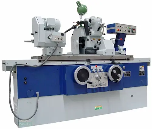
Fortunepacific UCG200PSA/UCG320PSA Automatic Cylindrical Grinders deliver high-precision machining for diverse components. Engineered for robust performance, these CNC cylindrical grinders feature rigid double-wheel design, oil-cooled spindles, and advanced Fanuc controls ensuring micron-level accuracy (IT grade 5 achievable, surface roughness Ra 0.2μm). Ideal for high-volume production of shafts, bearings, gears, and hydraulic parts, they excel in automotive, aerospace, and precision engineering. Key advantages include exceptional repeatability, minimized setup time via automatic wheel dressing/diameter compensation, and superior thermal stability. Core components comprise the heavy-duty cast iron bed, precision spindle headstock/tailstock, automatic feeding worktable, CNC system, and integrated coolant filtration. Users benefit from enhanced productivity, reduced scrap rates, and consistent quality for demanding OD grinding applications requiring tight tolerances and fine finishes. Search for automatic cylindrical grinder, CNC OD grinder, high precision grinding machine, production cylindrical grinder, Fortunepacific grinder.
Универсальные круглошлифовальные станки с ЧПУ Fortunepacific UCG200PSA/UCG320PSA обеспечивают высокоточную обработку валов, втулок, подшипников и сложных деталей. Эти автоматические станки для наружного шлифования оснащены двумя шлифовальными кругами, маслоохлаждаемыми шпинделями повышенной жесткости и системой Fanuc для точности до IT5 (Ra 0,2 мкм). Конструкция из высокопрочного чугуна гарантирует виброустойчивость и долговечность. Ключевые преимущества: высокая производительность, минимальное время переналадки благодаря автоматической правке кругов и компенсации износа, стабильность размеров в серии. Основные узлы: станина, бабка шпинделя и задняя бабка, столе автоматической подачи, ЧПУ, система СОЖ. Незаменимы в автомобилестроении, аэрокосмической отрасли, производстве гидравлики и точных механизмов. Ищите: круглошлифовальный станок с ЧПУ, автоматический шлифовальный станок, высокоточное шлифование валов, станок для чистовой обработки, Fortunepacific шлифовальный.
Las rectificadoras cilíndricas automáticas Fortunepacific UCG200PSA/UCG320PSA ofrecen rectificado de alta precisión para ejes, rodamientos y componentes complejos. Equipadas con doble muela, husillos refrigerados por aceite y controles Fanuc, logran precisiones IT5 y rugosidades Ra 0,2μm. Su robusta estructura de fundición garantiza estabilidad térmica y mínimas vibraciones. Ideales para producción en serie en automoción, aeroespacial e hidráulica, destacan por su repetibilidad, rápido cambio de pieza (gracias al carro automático) y bajo mantenimiento. Componentes clave: bancada, cabezal fijo y móvil, mesa de avance automático, CNC, sistema de filtración de refrigerante. Beneficios: máxima eficiencia, reducción de mermas y acabados superficiales perfectos para rectificado entre puntos y sin centros. Busque: rectificadora cilíndrica automática, rectificadora CNC exterior, máquina para rectificado de precisión, rectificadora Fortunepacific, rectificado de alta producción.
As retificadoras cilíndricas automáticas Fortunepacific UCG200PSA/UCG320PSA garantem usinagem de alta precisão para eixos, mancais e componentes hidráulicos. Com dois rebolos, fusos refrigerados a óleo e CNC Fanuc, atingem classe IT5 e rugosidade Ra 0,2μm. A estrutura rígida em ferro fundido assegura estabilidade térmica. Perfeitas para produção em série automotiva, aeroespacial e de precisão, oferecem repetibilidade excepcional, troca rápida de peças (via mesa automática) e baixo custo operacional. Componentes principais: base, cabeçote fixo e móvel, mesa de avanço automático, sistema CNC, filtragem de refrigerante. Vantagens: produtividade elevada, redução de retrabalho e acabamento superior para retificação cilíndrica externa com exigência de tolerâncias apertadas. Procure por: retificadora cilíndrica automática, retificadora CNC externa, máquina de retificar de alta precisão, retificadora Fortunepacific, retificação em série.
Mesin Gerinda Silinder Otomatis Fortunepacific UCG200PSA/UCG320PSA memberikan presisi tinggi untuk poros, bantalan, dan komponen industri. Dilengkapi dua roda gerinda, spindle berpendingin oli, dan kontrol Fanuc CNC, akurasi mencapai IT5 (kekasaran permukaan Ra 0,2μm). Konstruksi besi cor berat menjamin stabilitas dan umur panjang. Cocok untuk produksi massal otomotif, dirgantara, dan komponen presisi. Keunggulan: pengulangan akurat, waktu setup minim berkat penyetelan roda otomatis, dan efisiensi tinggi. Komponen utama: bed, headstock/tailstock, meja umpan otomatis, sistem CNC, filtrasi pendingin. Meningkatkan produktivitas, mengurangi cacat, dan konsistensi kualitas untuk aplikasi gerinda silinder luar (OD grinding) dan antara senter. Cari: mesin gerinda silinder otomatis, mesin gerinda CNC, mesin gerinda presisi tinggi, gerinda silinder Fortunepacific, mesin gerinda produksi.
دستگاه سنگ زنی استوانه ای اتوماتیک فورچون پسیفیک UCG200PSA/UCG320PSA با دو سنگ، اسپیندل روغن خنک و کنترل Fanuc، دقت IT5 و پرداخت سطح Ra 0.2μm را تضمین میکند. ساختار چدن سنگین و سیستم جبران سایش اتوماتیک سنگ، این دستگاه را برای تولید انبوه شفتها، یاتاقانها و قطعات صنعتی در خودرو، هوافضا و هیدرولیک ایدهآل میکند. مزایای کلیدی: تکرارپذیری عالی، زمان تنظیم کوتاه، کارایی بالا و قابلیت اطمینان. اجزای اصلی: بستر، هد ثابت و متحرک، میز پیشروی اتوماتیک، CNC، سیستم فیلتراسیون روانکار. افزایش بهرهوری، کاهش ضایعات و کیفیت ثابت برای سنگ زنی گردن میللنگ، پینها و سطوح استوانهای دقیق. جستجو کنید: دستگاه سنگ استوانه اتومات، سنگ محور CNC، دستگاه سنگ زنی دقیق، دستگاه سنگ فورچون پسیفیک، سنگ صنعتی.
Máy mài tròn tự động Fortunepacific UCG200PSA/UCG320PSA đạt độ chính xác cao IT5 (độ nhám Ra 0.2μm) nhờ 2 đá mài, trục chính làm mát dầu và điều khiển Fanuc. Kết cấu gang cứng vững, hệ thống bù mòn đá tự động, phù hợp sản xuất hàng loạt trục, bạc đạn, chi tiết ô tô, hàng không và thủy lực. Ưu điểm: độ lặp lại cao, thời gian thiết lập nhanh, hiệu suất ổn định. Thành phần chính: băng máy, ụ trước/ụ sau, bàn tiến dao tự động, hệ CNC, hệ thống lọc dung dịch. Tăng năng suất, giảm phế phẩm, chất lượng đồng đều cho mài tròn ngoài (OD grinding), mài cổ trục, chốt. Tìm kiếm: máy mài tròn tự động, máy mài CNC ngoài, máy mài chính xác cao, máy mài Fortunepacific, mài sản xuất.
เครื่องกลึงกลมอัตโนมัติ Fortunepacific UCG200PSA/UCG320PSA พร้อมล้อเจียรคู่ เพลาแบบใช้น้ำมันหล่อเย็น และระบบ Fanuc CNC ให้ความแม่นยำระดับ IT5 (ความหยาบผิว Ra 0.2μm) โครงสร้างเหล็กหล่อหนัก เสถียรภาพสูง ระบบลับคมล้อเจียรอัตโนมัติ เหมาะสำหรับผลิตชิ้นงานจำนวนมาก เช่น เพลา, แบริ่ง, ชิ้นส่วนยานยนต์, อวกาศ และไฮดรอลิก ข้อดี: ความแม่นยำซ้ำได้, เวลาตั้งเครื่องสั้น, ประสิทธิภาพการผลิตสูง องค์ประกอบหลัก: ฐานเครื่อง, หัวเครื่อง/ท้ายเครื่อง, โต๊ะป้อนอัตโนมัติ, ระบบ CNC, ระบบกรองน้ำหล่อเย็น เพิ่มผลผลิต, ลดของเสีย, คุณภาพสม่ำเสมอ สำหรับงานกลึงกลมภายนอก (OD grinding), งานคอเพลา, พิน ค้นหา: เครื่องกลึงกลมอัตโนมัติ, เครื่องกลึง CNC ภายนอก, เครื่องกลึงความแม่นยำสูง, เครื่องกลึง Fortunepacific, งานกลึงอุตสาหกรรม.
Mesin Pengisar Silinder Automatik Fortunepacific UCG200PSA/UCG320PSA menawarkan ketepatan IT5 (kekasaran permukaan Ra 0.2μm) dengan dua roda pengisar, spindle penyejuk minyak dan kawalan Fanuc CNC. Reka bentuk besi tuang berat, sistem pelaras roda automatik, sesuai untuk pengeluaran besar-besaran aci, galas, komponen automotif, aeroangkasa dan hidraulik. Kelebihan: kebolehulangan tinggi, masa persediaan singkat, kecekapan pengeluaran tinggi. Komponen utama: bed, headstock/tailstock, meja suapan automatik, sistem CNC, penapisan penyejuk. Meningkatkan produktiviti, mengurangkan kecacatan, kualiti konsisten untuk pengisaran silinder luar (OD grinding), leher aci, pin. Cari: mesin pengisar silinder automatik, mesin pengisar CNC, mesin pengisar ketepatan tinggi, pengisar Fortunepacific, pengisar pengeluaran.
AUTOMATA HENGERKÖRÜLŐGÉPEK UCG200PSA ÉS UCG320PSA – precíziós megoldásai a nehéziparnak. Ezek a CNC vezérlésű, automata henger- és homorúfelület-körülőrlő gépek kiválóak nagy pontosságú alkatrészek gyártásához, mint például csapágygyűrűk, tengelyek vagy szerszámok. Legfontosabb paraméterek: max. 200/320 mm őrlőátmérő, 500/1000/1500 mm őrlőhossz, ±0.001 mm pontosság, Fanuc kontroller. Struktúra: robusztus öntöttvas alap, automata orsóegység, hidrosztatikus vezetőcsapágyak, integrált mérési rendszer. Fő előnyök: kivételes felületi minőség (Ra 0.1 μm), magas termelékenység, könnyű beállítás, kiváló megbízhatóság. Ideális gépi alkatrészek, járműipar, szerszámgépgyártás számára. Keresők: automata körülőrlőgép, precíziós hengerlőgép, CNC körülőrlés, nagy pontosságú megmunkálás, ipari őrlőgép, hengerkő, körfelmérő, megmunkáló központ, hidrosztatikus körmegmunkáló, Fanuc gépi orsólás.
ΑΥΤΟΜΑΤΑ ΜΗΧΑΝΗΜΑΤΑ ΑΚΡΙΒΕΙΑΣ ΚΥΛΙΝΔΡΙΚΗΣ ΛΕΙΑΝΣΗΣ UCG200PSA & UCG320PSA: Επαναστατική τεχνολογία για απαιτητικές βιομηχανικές εφαρμογές. Αυτά τα πλήρως αυτοματοποιημένα, CNC μηχανήματα λείανσης κυλίνδρων και κωνικών επιφανειών προσφέρουν ασύγκριτη ακρίβεια (±0.001 mm) και επανάληψιμοτητα στην κατασκευή στοιχείων όπως ρουλεμάν, άξονες και εργαλεία. Βασικές παράμετροι: Μέγιστη διάμετρος λείανσης 200/320 mm, μήκος λείανσης 500/1000/1500 mm, ανάλυση 0.1 μm, Fanuc έλεγχος. Κατασκευή: Γερή χυτοσιδηρή βάση, αυτόματο σύστημα ατράκτου, υδροστατικές οδηγίες, ενσωματωμένο σύστημα μέτρησης. Πλεονεκτήματα: Εξαιρετική επιφανειακή ποιότητα (Ra 0.1 μm), υψηλή παραγωγικότητα, εύκολη ρύθμιση, ανθεκτικότητα. Ιδανικά για εξαρτήματα μηχανημάτων, αυτοκινητοβιομηχανία, εργαλειομηχανές. Λέξεις κλειδιά: αυτόματο μηχάνημα λείανσης, ακριβές κυλινδρικό μηχάνημα, CNC λείανση κύλινδρων, βιομηχανική λείανση υψηλής ακρίβειας, στροφικές μηχανές λείανσης, λειαντικές μηχανές με αυτόματο έλεγχο, υδροστατική λείανση, σύστημα αυτόματης μέτρησης λείανσης, Fanuc ελεγκτής λείανσης, γρήγορη παραγωγή ακριβών κυλίνδρων.
PLNĚ AUTOMATICKÉ CNC OBRÁBĚCÍ CENTRA PRO VÁLCOVÉ BRUSÍ UCG200PSA & UCG320PSA: Špičkové řešení pro dokončovací operace s extrémní přesností. Tyto automatické válcovací brusky na vnější a kuželové plochy jsou určeny pro sériovou výrobu vysoce přesných součástek jako ložiskové kroužky, hřídele nebo nástroje. Klíčové specifikace: max. brusný průměr 200/320 mm, brusná délka 500/1000/1500 mm, přesnost ±0.001 mm, rozlišení 0.1 μm, řídicí systém Fanuc. Konstrukce: robustní litinová základna, automatická vřetenová jednotka, hydrostatické vedení, vestavěný měřicí systém. Hlavní výhody: vynikající jakost povrchu (Ra 0.1 μm), vysoká produktivita, snadné seřízení, dlouhá životnost, minimální údržba. Perfektní pro automobilový průmysl, strojírenství, výrobu nástrojů. SEO: automatická bruska na válce, CNC válcová bruska, vysoce přesné broušení, průmyslová bruska, brusení čepů a hřídelí, bruska s hydrostatickými vodícími, bruska s integrovaným měřením, Fanuc řízení brusky, rychlé přebroušení, výrobní bruska velkých sérií, kuželová bruska.
ВИСОКОПРОИЗВОДИТЕЛНИ АВТОМАТИЧНИ ЦИЛИНДРИЧНИ ШЛАЙФМАШИНИ UCG200PSA & UCG320PSA: Идеално решение за финална обработка с микронна точност. Тези CNC управлявани машини за външно и конусно шлайфане са проектирани за масово производство на прецизни компоненти като лагери, валове, инструменти. Основни параметри: макс. Ø шлайфане 200/320 мм, дължина на шлайфане 500/1000/1500 мм, точност ±0.001 мм, разделителна способност 0.1 μm, управление Fanuc. Конструкция: здрава чугунена основа, автоматична шпинделна единица, хидростатични водачи, вградена измерителна система. Предимства: изключително качество на повърхността (Ra 0.1 μm), висока производителност, лесна настройка, надеждност. Приложение: автомобилна индустрия, общо машиностроене, инструментална промишленост. Търсени думи: автоматична шлайфовъчна машина, CNC цилиндрична шлайфовка, високоточково шлайфане, промишлено шлайфане, шлайфане на валове и шийки, шлайф машина с хидростатични водачи, шлайф с интегрирано измерване, Fanuc управление на шлайф, бързо пренареждане, шлайф за големи серии, конусо шлайфовъчен стан.
АУТОМАТСКЕ CNC ЦИЛИНДРИЧНЕ БРУСИЛИЦЕ UCG200PSA & UCG320PSA: Врхунско решење за прецизно спољно и конусно брушење. Ове потпуно аутоматске машине за брушење цилиндара и конуса омогућавају масовну производњу високо прецизних компоненти као што су лежајеви, осовине, алати. Кључни параметри: макс. пречник брушења 200/320 мм, дужина брушења 500/1000/1500 мм, тачност ±0.001 мм, резолуција 0.1 μm, Fanuc контрола. Конструкција: робусна ливена основа, аутоматска вретена, хидростатско вођење, интегрисани мерни систем. Предности: изуздан квалитет површине (Ra 0.1 μm), висока продуктивност, једноставно подешавање, дуговечност. Примењиве у аутомобилској индустрији, машиноградњи, производњи алата. Кључне речи: аутоматска брусилица за ваљке, CNC цилиндрична брусилица, прецизно брушење, индустријско брушење цилиндара, брушење осовина и вратова, брусилица са хидростатским вођењем, брусилица са уграђеним мерењем, Fanuc контрола брусилице, брза измена производње, брусилица за велике серије, конусна брусилица.
PLNE AUTOMATICKÉ VALCOVÉ BRÚSKY S CNC UCG200PSA & UCG320PSA: Špičkové zariadenia pre vysokopresné vonkajšie a kužeľové brúsenie. Tieto CNC riadené automatické brúsky na valčeky a kužele sú určené pre sériovú výrobu presných komponentov ako ložiskové krúžky, hriadele, nástroje. Parametre: max. brúsny priemer 200/320 mm, dĺžka brúsenia 500/1000/1500 mm, presnosť ±0.001 mm, rozlíšenie 0.1 μm, riadenie Fanuc. Konštrukcia: robustná liatinová základňa, automatická vretenová jednotka, hydrostatické vedenie, vstavaný merací systém. Výhody: vynikajúca kvalita povrchu (Ra 0.1 μm), vysoká produktivita, ľahké nastavenie, spoľahlivosť. Využitie: automobilový priemysel, strojárstvo, výroba nástrojov. SEO: automatická brúska na valčeky, CNC valcová brúska, vysoko presné brúsenie, priemyselná brúska, brúsenie čapov a hriadeľov, brúska s hydrostatickými vedeniami, brúska s integrovaným meraním, Fanuc riadenie brúsky, rýchla zmena výroby, brúska pre veľké série, kužeľová brúska, automatické ostrenie vreten.
AUTOMATSKE BRUSILICE ZA CNC CILINDRIČNO BRUŠENJE UCG200PSA & UCG320PSA: Vrhunska rješenja za vanjsko i konusno brušenje iznimne preciznosti. Ove potpuno automatizirane brusilice za cilindre i konuse omogućuju masovnu proizvodnju visokopreciznih komponenti poput ležajeva, osovina, alata. Glavni parametri: max. promjer brušenja 200/320 mm, duljina brušenja 500/1000/1500 mm, točnost ±0.001 mm, razlučivost 0.1 μm, Fanuc upravljanje. Konstrukcija: robusna temeljna ploča od lijevanog željeza, automatska glavčina, hidrostatski vodilici, integrirani mjerni sustav. Prednosti: izvrsna kvaliteta površine (Ra 0.1 μm), visoka produktivnost, jednostavno podešavanje, izdržljivost. Primjena: automobilska industrija, strojogradnja, alatništvo. Ključne riječi: automatska brusilica za valjke, CNC cilindrična brusilica, precizno brušenje, industrijsko brušenje, brušenje osovina i vratila, brusilica s hidrostatskim vodilicama, brusilica s ugrađenim mjerenjem, Fanuc kontrola brusilice, brza promjena proizvodnje, brusilica za velike serije, konusno brušenje, energetski učinkovita brusilica.
POPOLNOMA AVTOMATIZIRANI CNC VALJNI BRUŠILNIKI UCG200PSA & UCG320PSA: Vrhunska rešitev za zunanje in stožčno brušenje mikronske natančnosti. Ti avtomatski brusilni stroji za valje in stožce so namenjeni serijski proizvodnji visoko natančnih komponent, kot so ležajni obroči, gredi, orodja. Ključne specifikacije: max. premer brušenja 200/320 mm, dolžina brušenja 500/1000/1500 mm, natančnost ±0.001 mm, ločljivost 0.1 μm, Fanuc krmiljenje. Konstrukcija: robustno lito železno ogrodje, avtomatska vretena, hidrostatični vodila, vgrajen merilni sistem. Prednosti: izjemna kakovost površine (Ra 0.1 μm), visoka produktivnost, enostavno nastavljanje, zanesljivost. Uporaba: avtomobilska industrija, splošno strojništvo, orodjarstvo. Iskalni izrazi: avtomatska valjna brusilnik, CNC cilindrična brusilnica, visoko natančno brušenje, industrijsko brušenje, brušenje gredi in ojnic, brusilnik s hidrostatičnimi vodili, brusilnik z vgrajenim merjenjem, Fanuc krmilnik za brusilnike, hitra prenamestitev, brusilnik za velike serije, konusno brušenje.
ВИСОКОТОЧНІ АВТОМАТИЧНІ КРУГЛОШЛІФУВАЛЬНІ ВЕРСТАТИ UCG200PSA ТА UCG320PSA: Провідне рішення для зовнішнього та конічного шліфування з надвисокою точністю. Ці верстати з ЧПУ керуванням призначені для серійного виробництва прецизійних деталей, таких як підшипникові кільця, вали, інструменти. Основні параметри: макс. Ø шліфування 200/320 мм, довжина шліфування 500/1000/1500 мм, точність ±0.001 мм, роздільна здатність 0.1 μm, система керування Fanuc. Конструкція: міцна чавунна станина, автоматична шпиндельна бабка, гідростатичні напрямні, вбудована вимірювальна система. Переваги: відмінна якість поверхні (Ra 0.1 μm), висока продуктивність, просте налаштування, надійність. Застосування: автомобільна промисловість, машинобудування, інструментальне виробництво. Ключові слова: автоматичний круглошліфувальний верстат, верстат ЧПУ для круглого шліфування, високоточне шліфування, промислове шліфування, шліфування валів та шийок, шліфувальний верстат з гідростатичними напрямними, верстат з інтегрованим вимірюванням, керування Fanuc шліфуванням, швидке переналагодження, шліфувальний верстат для великих серій, конічне шліфування, автономна система охолодження шліфувальних верстатів.